Benchmarking an AliExpress MT3608 Boost Converter
Over the past years, I have obtained a variety of buck and boost converters, mostly from AliExpress and ebay. Now that I finally have a way of characterizing them, I am curious about their performance in practice.
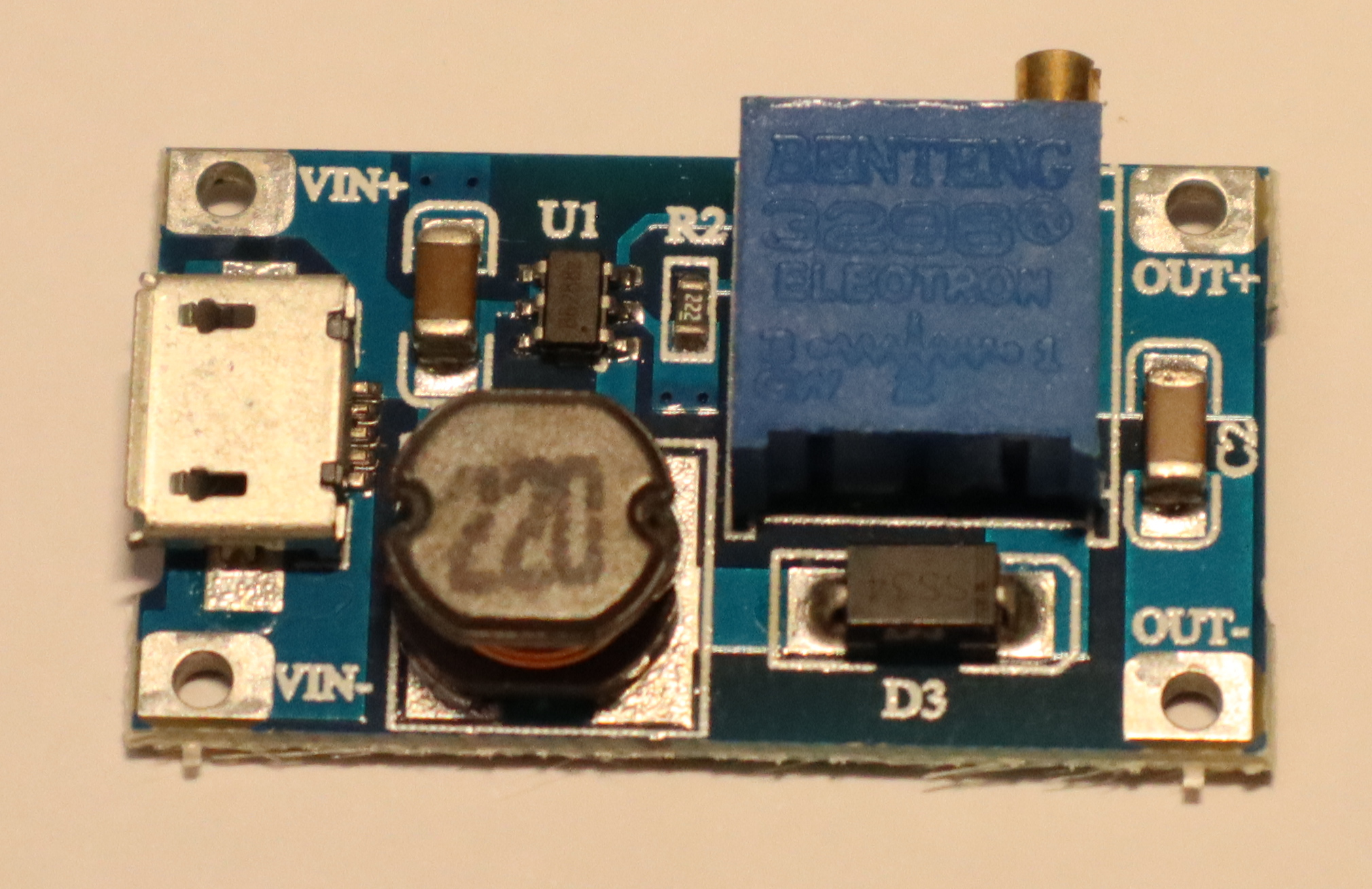
Today's specimen is an MT3608-based step up / boost converter from AliExpress. It's sold with a microUSB input, so boosting 5V from USB to 9V or 12V is a likely application. However, given its low quiescent current, it also seems like a good candidate for boosting ~3.7V from a LiIon battery to 5V for USB.
Specs
Advertised ratings vary. The following conservative estimates might be close to reality.
- Input range: 3V .. 24 V
- Output range: 5V .. 28V
- Maximum input current: 0.8 A (1 A?) continuous, 2 A burst.
- Quiescent current: ~100µA
- Maybe: thermal overload protection
- Maybe: internal 4 A over-current limit
The boost modules I have use a multi-turn potentiometer to configure output voltage.
Application
In this setup, I focused on boosting LiIon voltage to 5V for USB output. LiIon voltage typically ranges from 3.0 to 4.2 V -- I went up to 4.5 V just to gather some more data.
Caution
I took reasonable care to calibrate my readings, but will not give any guarantees. The following results might not be close to reality, and might be affected by knock-off chips and sub-par circuit design.
Output Voltage Stability
Both input voltage and output power of a boost converter can vary over time, especially when powered via a LiIon battery. Its output voltage should remain constant in all cases, or only sag a little under load. Most importantly, it should never exceed its idle output voltage – otherwise, connected devices may break.

Up to about 400 mA output current, the converter is well-behaved. Beyond that (i.e., once its input current exceeds 800mA), its output voltage is all over the place – both below and above the set point. With an observed range of 4.5 to 5.7 V, it is also way outside the USB specification, which states that devices must accept 4.5 to 5.2 V.
So, I'd strongly advise against using this chip to power USB devices that may draw more than a few hundred mA.
At 9V and 12V output, I did not notice issues at up to 400 mA, but did not measure anything beyond that. Also, the measurement setup for these two benchmarks was a bit less accurate.


Efficiency
In low-power operation (no more than a few hundred mA), the converter is quite efficient. Beyond that (i.e., in the unstable output voltage area) its efficiency varies as well.

Further Observations
Once input current exceeds 800mA, the devices I have here emit a relatively loud, high-frequency noise.
TL;DR
Exercise caution to avoid frying USB devices.
Building a test setup for benchmarking buck/boost converters
I have a growing collection of mostly cheap buck/boost converters and am kinda curious about their efficiency and output voltage stability.
Measuring that typically entails varying input voltage and output current while logging input voltage (V_i), input current (I_i), output voltage (V_o), and output current (I_o).
For each reading, efficiency is then defined as (V_o · I_o) / (V_i · I_i) · 100%.
+-------------+
|             |
|    Input    |
|             |
+---+-----+---+
    |     |
    |     +-+
    |      I_i
    |     +-+
    +-V_i-+
    |     |
+---+-----+---+
|             |
|  Converter  |
|    under    |
|    Test     |
|             |
+---+-----+---+
    |     |
    +-V_o-+
    |     +-+
    |      I_o
    |     +-+
    |     |
+---+-----+---+
|             |
|    Output   |
|             |
+-------------+
The professional method of obtaining these values would probably involve a Source/Measure Unit (SMU) with 4-wire sensing and remote control to automatically vary input voltage / output current while logging voltage and current readings to a database. I do not have such a device here -- first, they tend to cost €€€€ or even €€€€€, and second, many of those are more at home in the single-digit Watt range. I do, however, have a lab PSU with remote control and access to output voltage and current readings, a cheap electronic load (without remote control), an ADS1115 16-Bit ADC for voltage measurements, and an ATMega328 for data logging. This allows me to manually set a constant output current I_o and then automatically vary the input voltage while logging V_i, I_i, and V_o.
There is just one catch: The ADS1115 cannot measure voltages that exceed its input voltage (VCC, in this case 5V provided via USB). A voltage divider solves this, at the cost of causing a small current to flow through the divider rather than the buck/boost converter under test. In my case, I only had 10kΩ 1% resistors at hand, and used them to build an 8:1 divider for both differential ADS1115 input channels. This way, I can measure up to 40V, with up to 500µA flowing through the voltage divider. Compared to the 100 mA to several Amperes I intend to use this setup with, that is negligible.
V_i + ----+                  VCC  GND           VCC  GND
         70k                   |  |               |  |
          +--+ +------------+  |  | +-----------+ |  |
         10k +-+A0          +--+  | |           +-+  |
V_i - ----+-+  |            |     | |           |    |
            +--+A1          +-----+ |           +----+
V_o + ----+    |  ADS1115   |       | ATMega328 |
         70k+--+A2       SCL+-------+SCL      TX+--------to USB-Serial converter
          +-+  |            |       |           |
         10k +-+A3       SDA+-------+SDA        |
V_o - ----+--+ +------------+       +-----------+
Of course, this whole contraption is far from certifiably accurate or ppm-safe, and even less so when looking at the real-world setup on my desk.
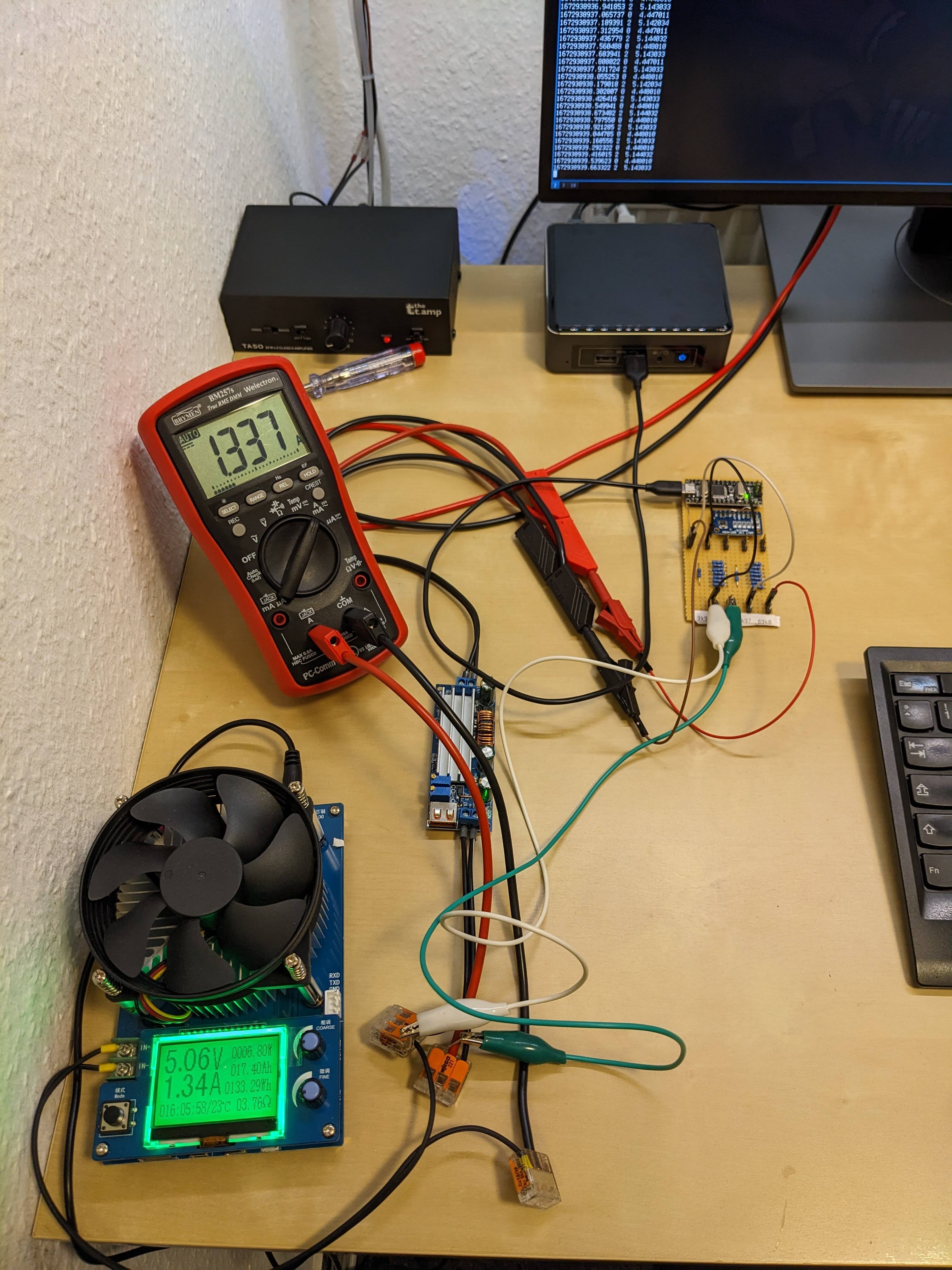
I did however find it to be accurate within ±10mV after some calibration, so it is sufficient to determine whether a converter is in the 80% or 90% efficiency neighbourhood and whether it actually outputs the configured 5.2V or decides to go up to 5.5V under certain load conditions. Luckily, that is all I need.
The bottom line here is: If you have sufficiently simple / low-accuracy requirements, cheap components that may already be lying around in some forgotten project drawer can be quite useful. Also, I really like how easy working with the ADS1115 chip is :)
Logging HomeAssistant data to InfluxDB
I'm running a Home Assistant instance at home to have a nice graphical sensor overview and home control interface for the various more or less DIY-ish devices I use. Since I like to monitor the hell out of everything, I also operate an InfluxDB for longer-term storage and fancy plots of sensor readings.
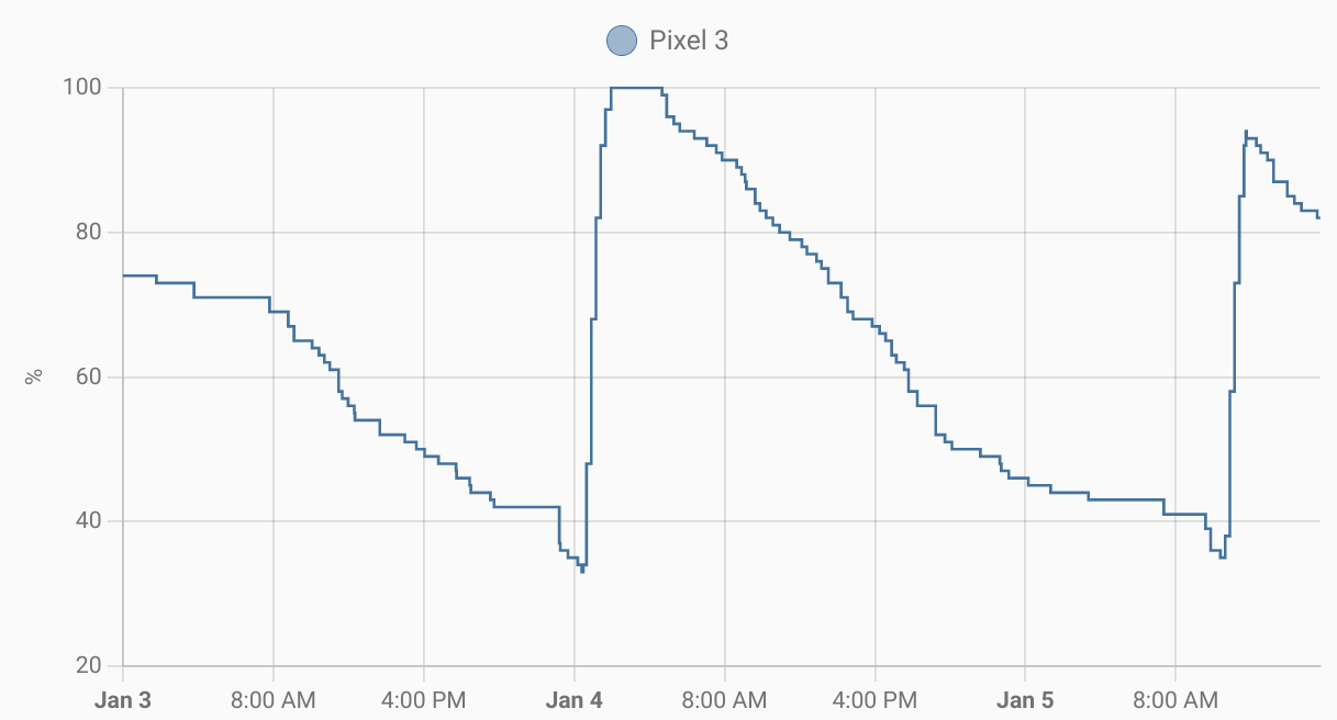
Most of my ESP8266 and Raspberry Pi-based DIY sensors report both to MQTT (→ Home Asisstant) and InfluxDB. For Zigbee devices I'm using a small script that parses MQTT messages (intended for Zigbee2MQTT ↔ Home Assistant integration) and passes them on to InfluxDB. However, there are also devices that are neither DIY nor using Zigbee, such as the storage and battery readings logged by the Home Asisstant app on my smartphone.
Luckily, Home Assistant has a Rest API that can be used to query device states (including sensor readings) with token-based authentication. So, all a Home Assistant to InfluxDB gateway needs to is query the REST API periodically and write the state of all relevant sensors to InfluxDB. For binary sensors (e.g. switch states), this is really all there is to it.
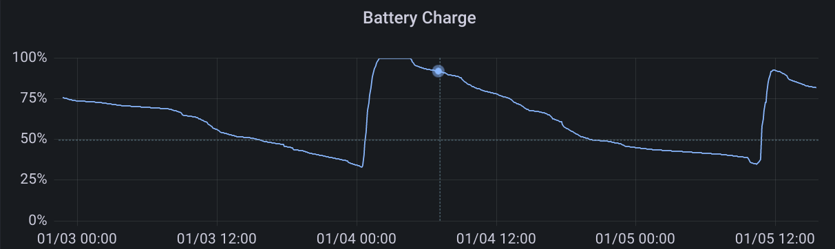
For numeric sensors (e.g. battery charge), especially with an irregular update schedule, the script should take its last update into account. This way, InfluxDB can properly interpolate between data points, producing (IMHO) much prettier graphs than Home Assistant does. If you also want to extend your Home Assistant setup with InfluxDB, c hass to influxdb may be a helpful starting point.
2024