PowerCore+ 26800 Teardown
After nearly five years of service, my PowerCore+ 26800 power bank broke down recently. After a few weeks with an only intermittently working USB-C output, it stopped providing power altogether – and also stopped accepting power to recharge the battery pack, providing a distinct smell of magic smoke and an internal short circuit instead.
As the power bank is out of warranty anyways, this is a good opportunity for a happy little autopsy.
Caution: This powerbank contains nearly 100 Wh worth of LiIon cells. In normal operation, the (dis)charge PCB is in charge of battery management tasks like short circuit prevention. Disassembling the device exposes raw LiIon cells, which typically do not contain separate protection circuitry. Puncturing, shorting, or otherwise mishandling one of those can lead to fire. Don't disassemble a powerbank unless you know what you are doing.
Case Teardown
The top and bottom plastic covers are glued on and can be pried open with moderate effort, revealing four screws each.
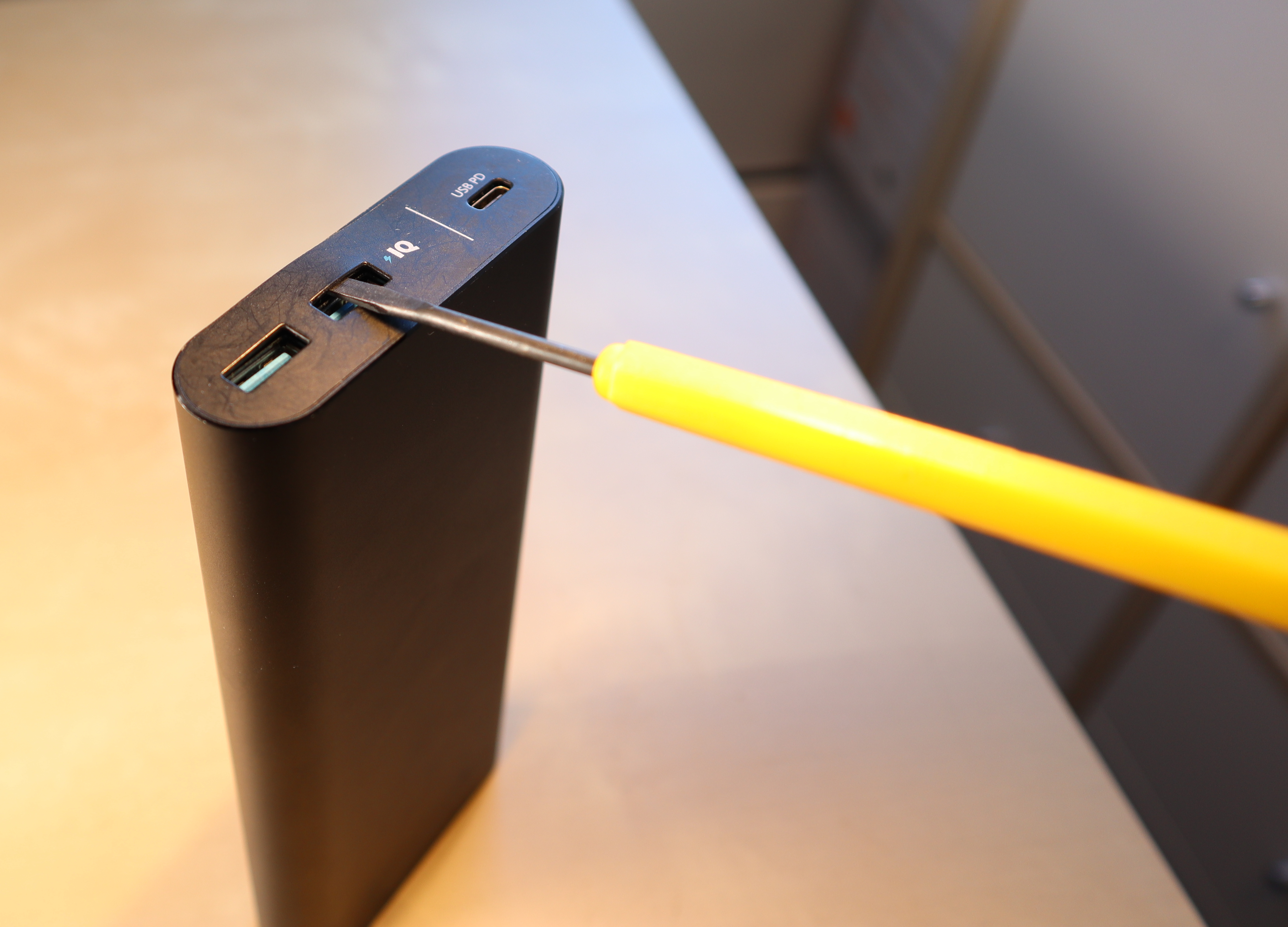

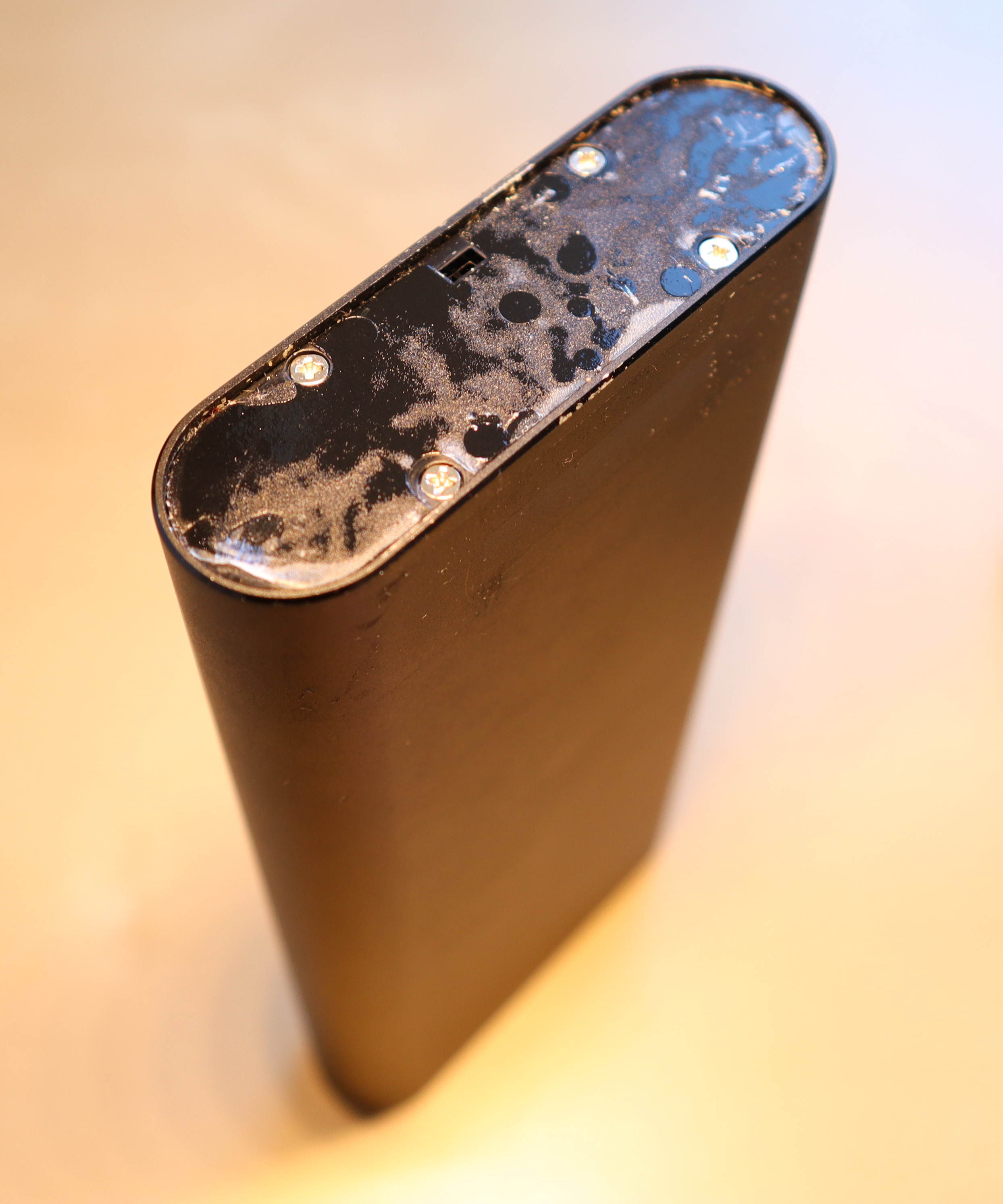
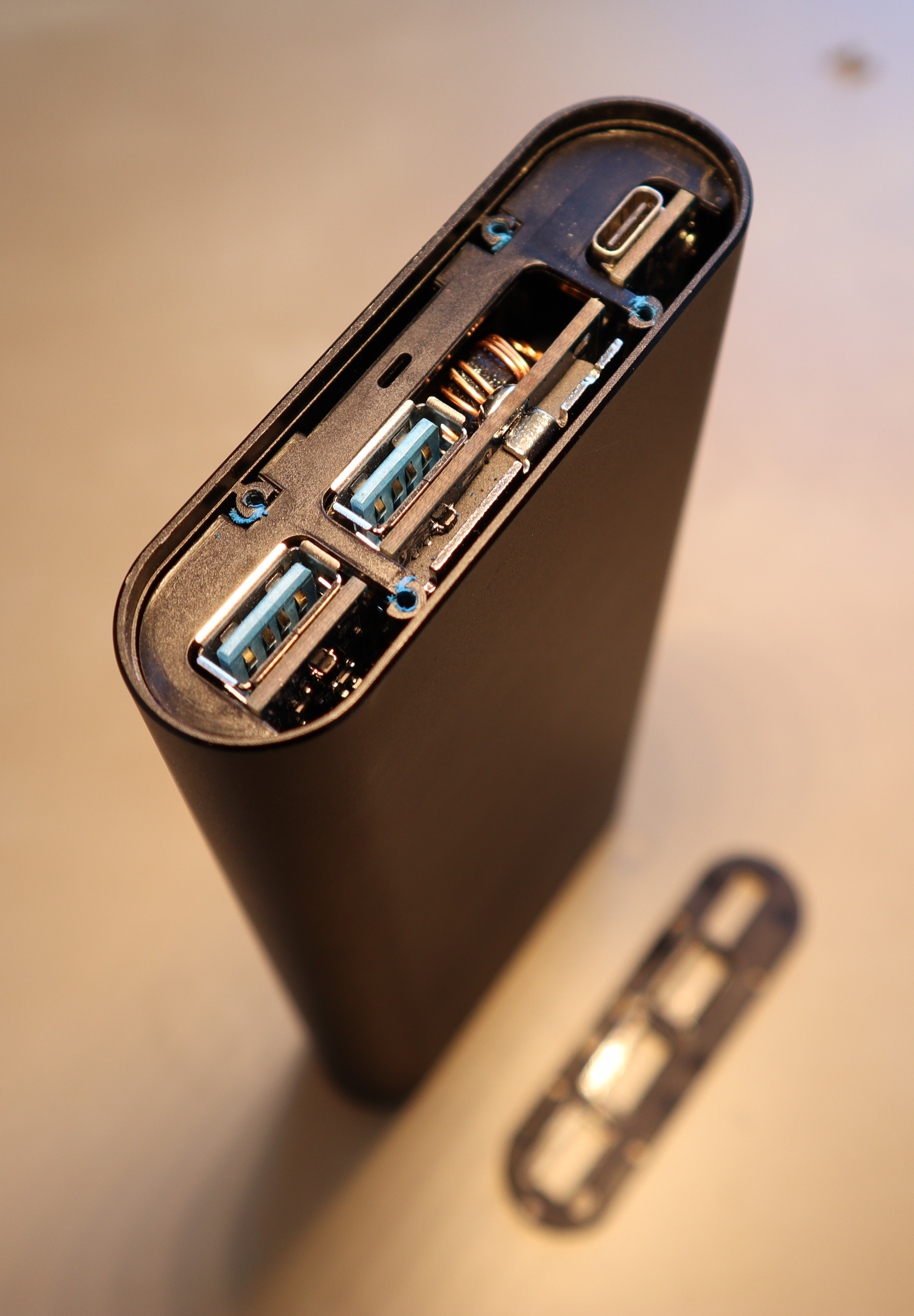
After removing the screws and a second (also glued-on) top cover, you can push onto the connector board (top) to coax the cell and PCB assembly out of the case. A good spot for application of force is the plastic surface next to the USB-C port. It's a tight fit, so the assembly won't slide out by itself. Pushing from the bottom won't work.

The LiIon cell layout is 2S4P with balancing. The cells are labeled “LGGBF1L1865”, which appears to correspond to LG's INR18650F1L model.
Each cell is rated as follows:
- Nominal capacity: 3.3 Ah at 3.63 V (12 Wh)
- Charge current: 0.3C (975 mA) nominal, 0.5C (1625 mA) maximum, 4.2 V / 50 mA cut-off
- Discharge current: 0.2C (650 mA) nominal, up to 1.5C (4875 mA) maximum, 2.5V cut-off
For the 2S4P pack, this gives:
- Nominal capacity: 13.2 Ah at 7.26 V (96 Wh)
- Charge current: 0.3C (3.9 A) nominal, 0.5C (6.5 A) maximum, 200mA cut-off
- Discharge current: 0.2C (2.6 A) nominal, up to 1.5C (19.5 A) maximum, 5.0V cut-off
For comparison, the powerbank's product specifications state:
- Capacity: 26.8 Ah at 3.6V (96 Wh)
- Input: Up to 27 W (9 V, 3 A) → Charging probably uses less than 0.3C
- Output: Up to 25 W (20 V, 1.25 A) via USB-C + about 20 W (5 V, 2 A) via USB-A → Discharge current is up to 0.5C (6.6 A)
My mostly discharged cells read 3.18 and 3.20V, respectively, so the cell management chip seems to be operating in a rather conservative voltage range. This should be good for longevity.


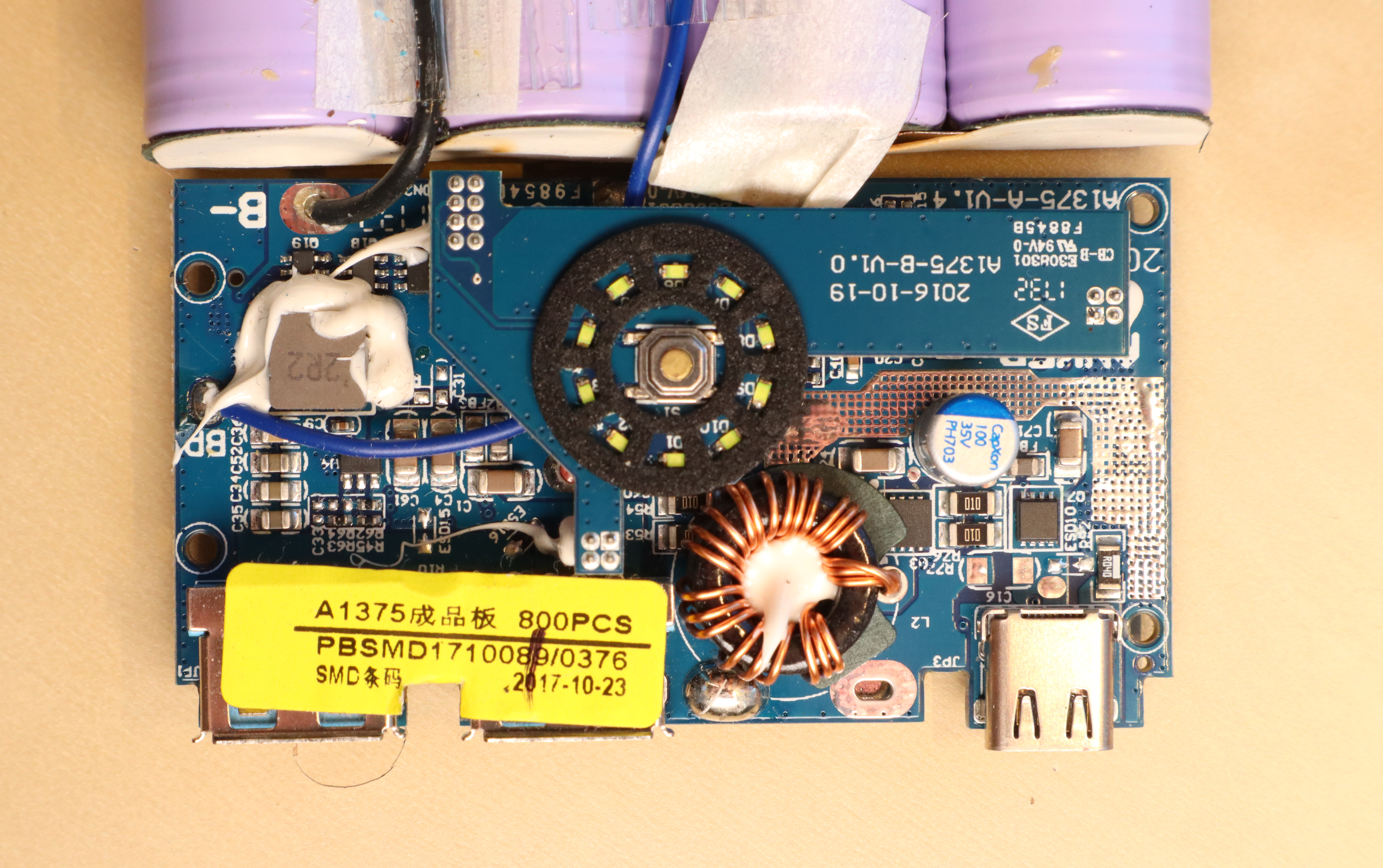
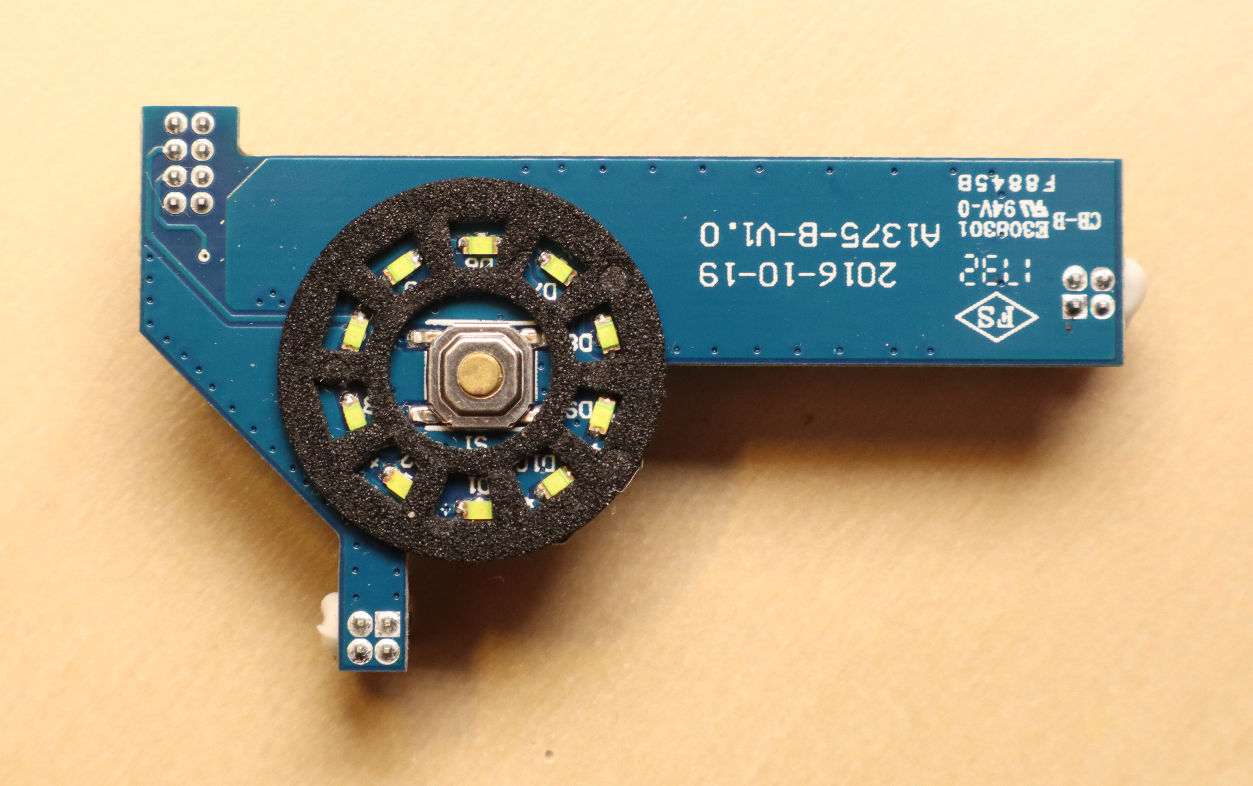
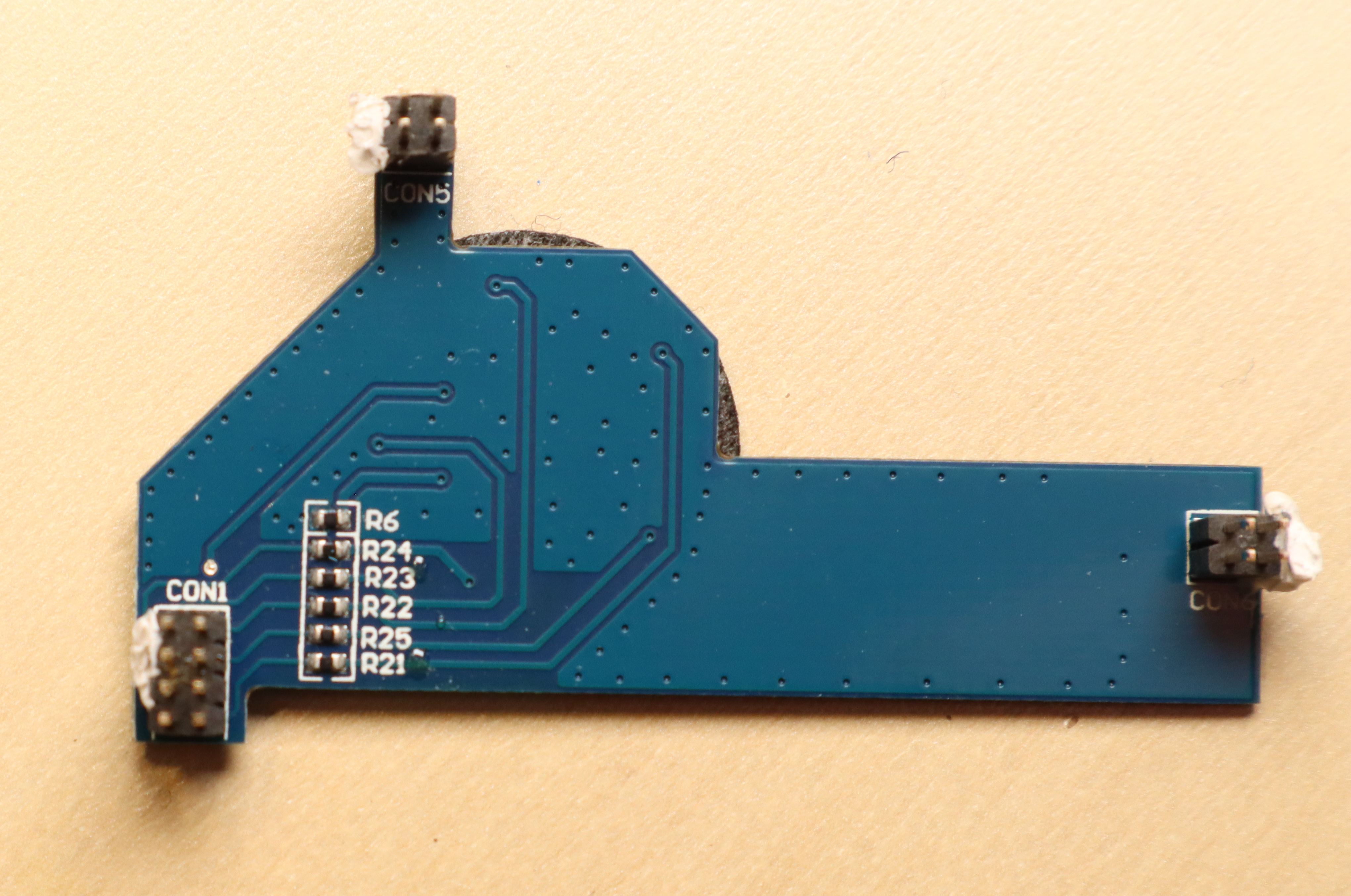
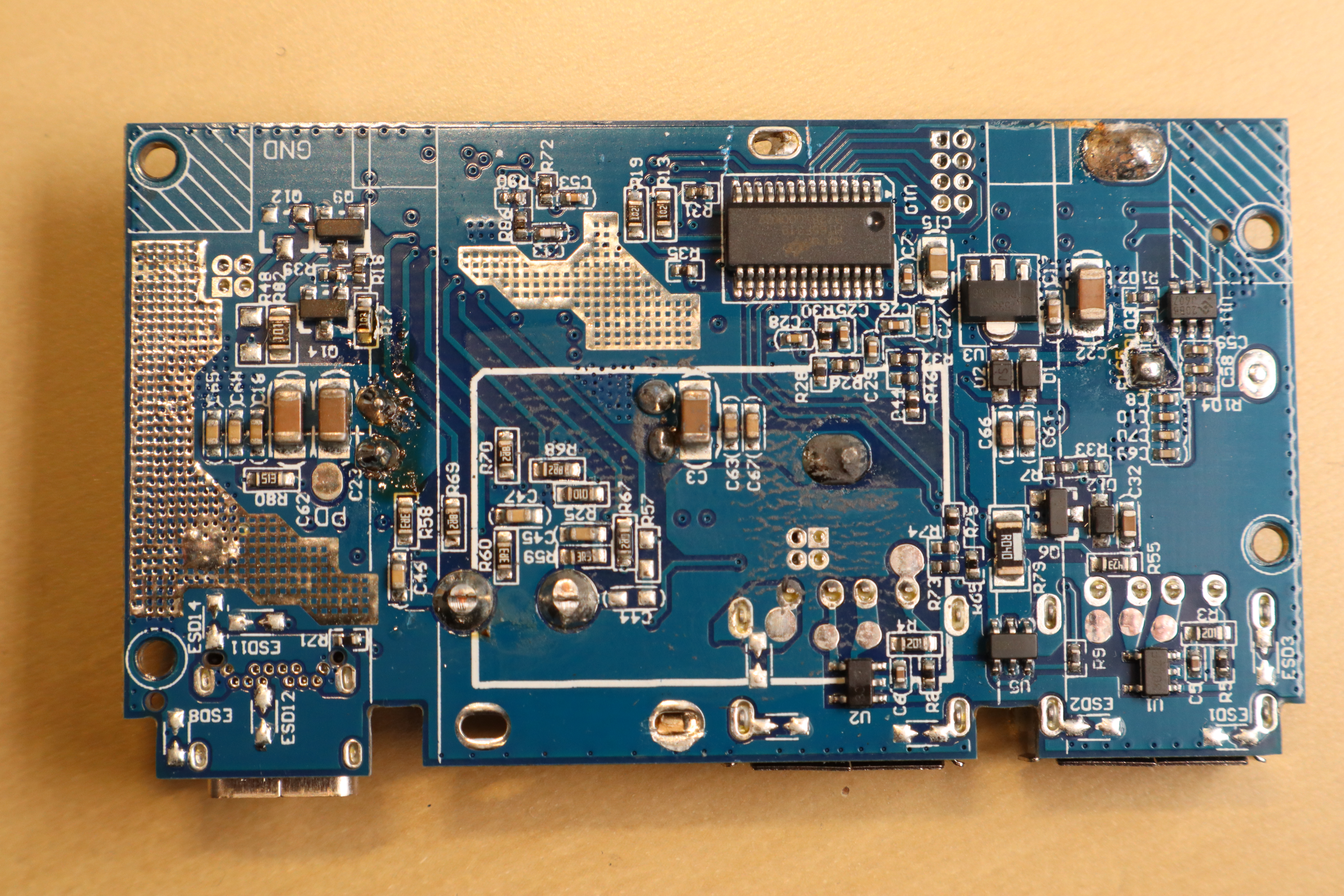
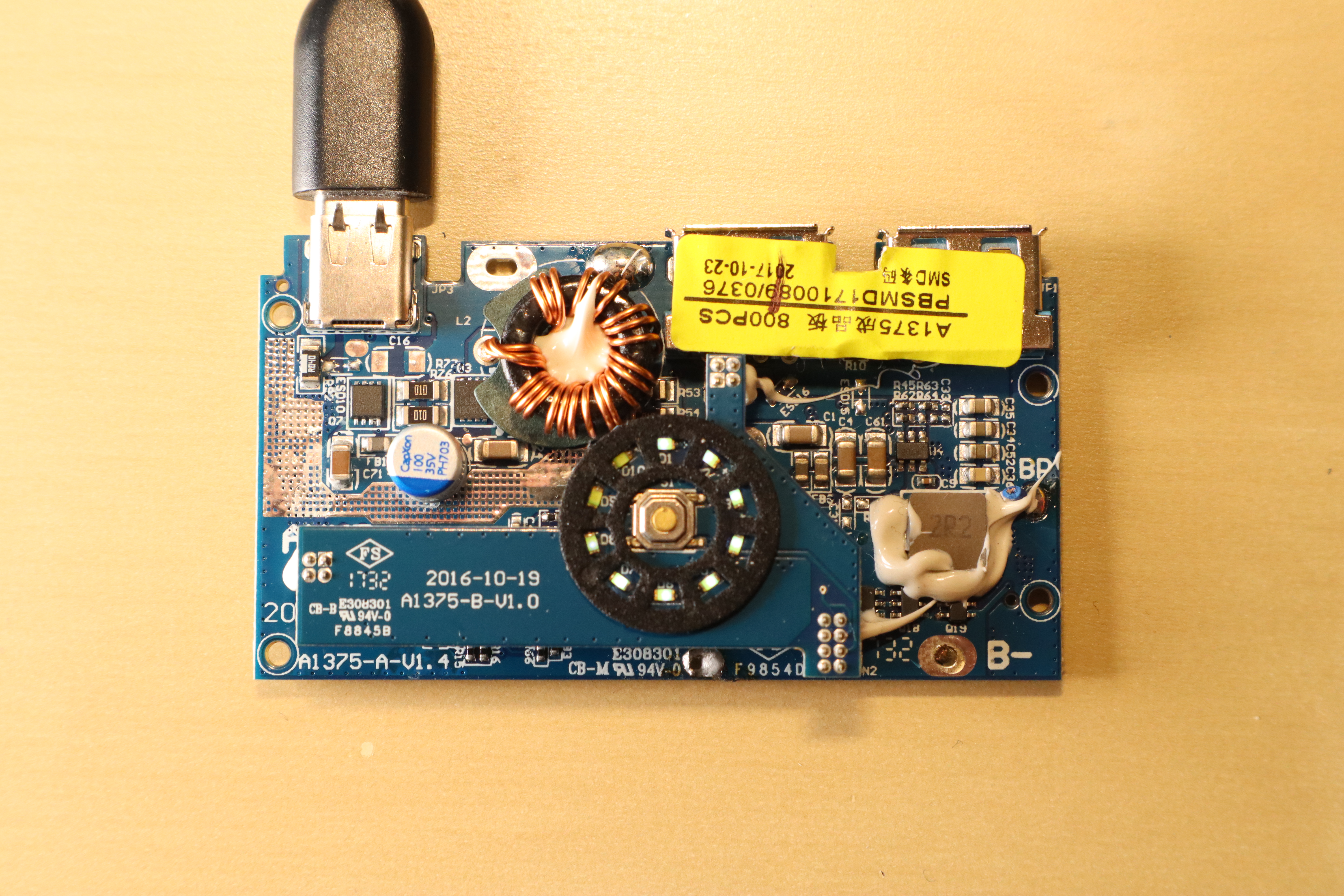
PCB Teardown
The top PCB is only responsible for LED output and button input.
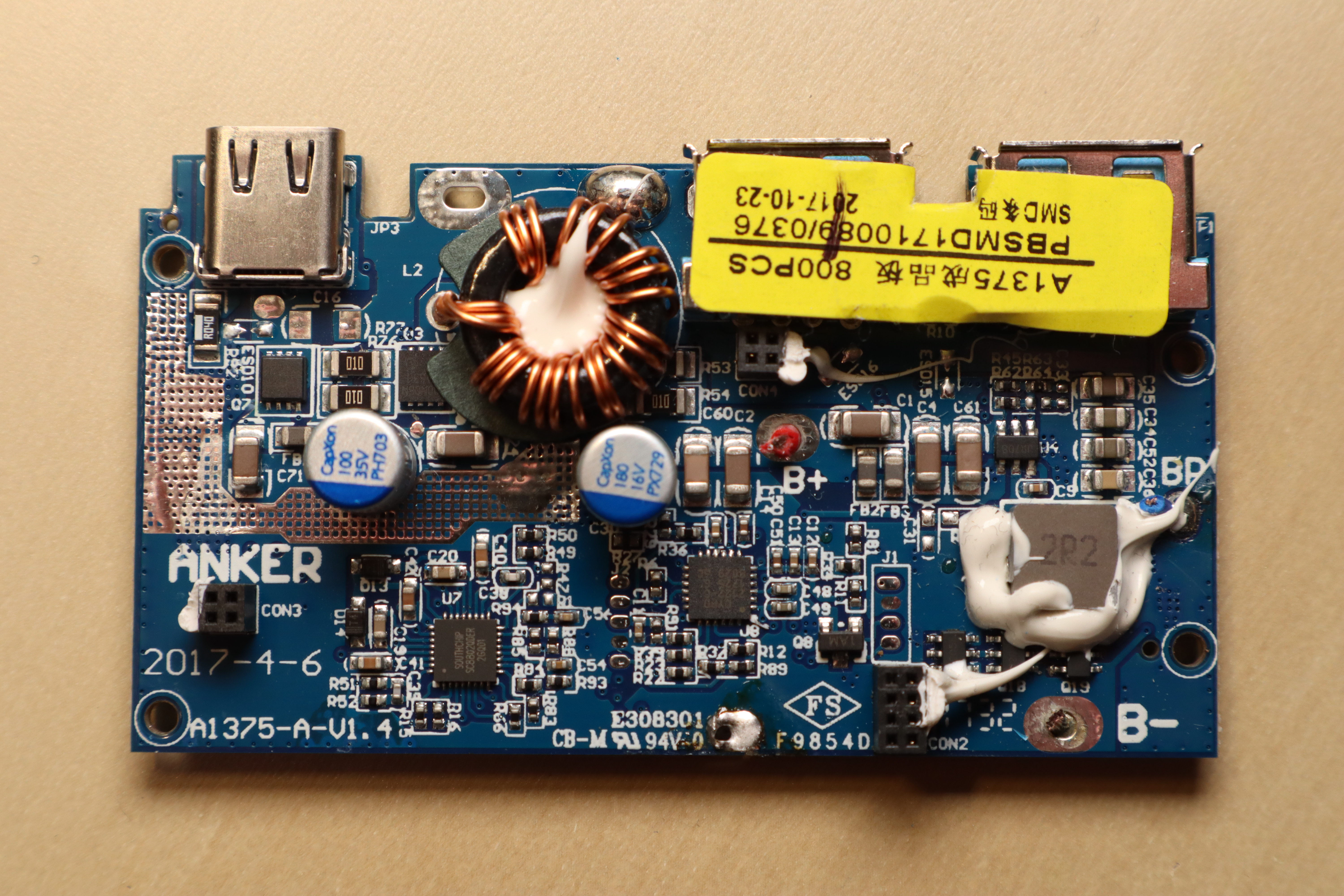
The bottom PCB includes an SC8802 synchronous, bi-directional, 4-switch buck-boost charger controller and a HT66F319 microcontroller.
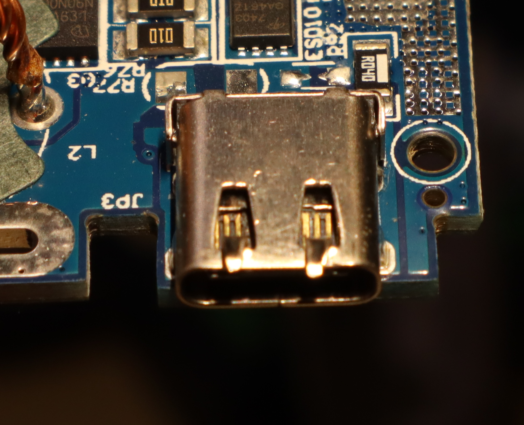
The Culprit
Even with disconnected batteries, there's a two ohm short circuit between USB-C VCC and USB-C GND. The culprit turned out to be the USB-C plug itself.
USB-C plugs contain a tiny PCB with contacts on both sides that the cable slides onto. In this case, the lower (recessed, non-contact) part of the PCB is embedded into a metal piece for stability. Over time, the metal piece had moved towards the contacts, eventually causing an electrical connection and thus a short circuit. After moving it back, the power bank is working again. I don't trust the USB-C port anymore, though.
Thoughts on embedded environmental sensors
Over the past few years, I've been frequently working with I²C environmental sensors for measuring temperature, humidity and so on. Here are some thoughts and observations of sensors and breakout boards I made along the way. Note that this is by no means a proper professional review, you should take everything posted here with a grain of salt.
Minimal drivers for all sensors listed here can be found in the multipass project.
Sensors and Datasheet specs
| Sensor | Property | Resolution | Accuracy | Range |
|---|---|---|---|---|
| AM2320 | Temperature [°c] Humidity [%] |
0.1 0.1 |
±0.5 ±3 |
-40 .. 80 0 .. 99.9 |
| BME280 | Temperature [°c] Humidity [%] Pressure [hPa] |
0.01 0.008 0.18 Pa |
±1 @ 0 .. 65 ±3 @ 20 .. 80 ±1 |
-40 .. 85 0 .. 100 300 .. 1100 |
| BME680 | Temperature [°c] Humidity [%] Pressure [hPa] VOC [IAQ] |
0.01 0.008 0.18 Pa 1 |
±1 @ 0 .. 65 ±3 @ 20 .. 80 ±0.6 ±15% ±15 |
-40 .. 85 0 .. 100 300 .. 1100 0 .. ? |
| CCS811 | TVOC [ppb] | 1 | ? | 0 .. 1187 |
| HDC1080 | Temperature [°c] Humidity [%] |
0.1 0.1 |
±0.2 @ 5 .. 60 ±2 |
-40 .. 125 0 .. 100 |
| LM75B | Temperature [°c] | 0.125 | ±2 / ±3 | -55 .. +125 |
Notes
AM2320
- I²C readout is a multi-step process with special timing requirements
- Reported humidity appears to be far too low on some devices
BME280
- max 3.6V; some breakout boards provide LDO and level shifters for 5V operation
- Supports both I²C and SPI; operating mode selected by CSB value
- The breakout boards I am aware of connect VCC to both VDD and VDDIO, making power sequencing with respect to CSB a tad difficult. On some of them, I had to power CSB before providing power to VCC to ensure that the chip starts up in I²C mode.
BME680
- IAQ calculation is only possible with a closed-source BLOB provided by Bosch SensorTec, setting that up on a Raspberry Pi is quite easy though.
CCS811
- In addition to Total Volatile Organic Compound (TVOC), the sensor reports “equivalent CO₂” (eCO₂) data calculated from TVOC. I found these to be unreliable.
LM75B
- readout is trivial
- SMBus compatible: using it on a Raspberry Pi is a simple as
i2cget -y 1 0x48 0x00 w
HDC1080
- reported humidity appears to be a tad too low
Handling USB-serial connection issues on some ESP8266 dev boards
Depending on the configuration of a few GPIO pins during reset, ESP8266 chips can boot into a variety of modes. The most common ones are flash startup (GPIO0 low → execute the program code on a flash chip connected to the ESP8266) and UART download (GPIO0 high → transfer program code from UART to the flash chip).
Most development boards use the serial DTR and RTS lines of their usb-serial converter to allow reset (and boot mode selection) of the ESP8266 by (de)assertion of the DTR/RTS signals. esptool also uses this method when uploading new firmware to the flash.
Usually, things just work™ and an ESP8266 can be used with esptool, nodemcu-uploader, miniterm/screen, and other software. If esptool/nodemcu-uploader work, but miniterm/screen do not (and show repeating gibberish or nothing at all instead), the reason may be unusual DTR/RTS behaviour. I found manual control of DTR/RTS to help in this case:
- Connect to the serial device
- de-assert DTR
- de-assert RTS
- receive a working UART connection
For example, in pyserial-miniterm these signals can be set on startup:
pyserial-miniterm --dtr 0 --rts 0 /dev/ttyUSB0 115200
They can also be toggled at runtime via Ctrl+T Ctrl+D (DTS) and Ctrl+T Ctrl+R (RTS).
$ pyserial-miniterm /dev/ttyUSB0 115200
--- Miniterm on /dev/ttyUSB0  115200,8,N,1 ---
--- Quit: Ctrl+] | Menu: Ctrl+T | Help: Ctrl+T followed by Ctrl+H ---
--- DTR inactive ---
--- RTS inactive ---
Hello, World!
Vindriktning is a cheap USB-C powered particle sensor that uses three colored LEDs to indicate the amount of PM2.5 (i.e., particulate matter with a diameter of less than 2.5µm) as a proxy for indoor air quality. By default, it simply measures PM2.5 and indicates whether air quality is good, not so good, or poor – there is no digital read-out of PM2.5 values.
Luckily, adding an ESP8266 to integrate it with MQTT, HomeAssistant, InfluxDB, or other software is quite easy. However, while most examples use Arduino's C++ dialect for programming, I personally prefer to stick to the NodeMCU Lua firmware on ESP8266 boards. Here is my basic readout code for reference.
function uart_callback(data)
    if string.byte(data, 1) ~= 0x16 or string.byte(data, 2) ~= 0x11 or string.byte(data, 3) ~= 0x0b then
        print("invalid header")
        return
    end
    checksum = 0
    for i = 1, 20 do
        checksum = (checksum + string.byte(data, i)) % 256
    end
    if checksum ~= 0 then
        print("invalid checksum")
        return
    end
    pm25 = string.byte(data, 6) * 256 + string.byte(data, 7)
    print("pm25 = " .. pm25)
end

function setup_uart()
    port = softuart.setup(9600, nil, 2)
    port:on("data", 20, uart_callback)
end

setup_uart()
This code assumes that the Vindriktning's TX pin is connected to ESP8266 GPIO4 (labeled "D2" on most esp8266 devboards). As the ESP8266 only has a single RX channel, which we reserve for programming and debugging, I'm using a Software UART implementation. At 9600 baud, that's not an issue.
If you're running a MediaWiki 1.35 with PluggableAuth and LdapAuthentication2, there's two ways of supporting login for LDAP accounts and local accounts.
In LocalSettings.php, set either
$wgPluggableAuth_EnableLocalLogin = true;
or
$LDAPAuthentication2AllowLocalLogin = true;
They have slightly different UI, but work pretty much the same from a login perspective. However, the LDAPAuthentication2 variant does not support local account creation.
So, if you're getting an error message along the lines of "The supplied
credentials could not be used for account creation" when trying to register
a local account on your MediaWiki instance, you may need to set
$wgPluggableAuth_EnableLocalLogin = true; in your LocalSettings.php.