After nearly five years of service, my PowerCore+ 26800 power bank broke down recently. After a few weeks with an only intermittently working USB-C output, it stopped providing power altogether – and also stopped accepting power to recharge the battery pack, providing a distinct smell of magic smoke and an internal short circuit instead.
As the power bank is out of warranty anyways, this is a good opportunity for a happy little autopsy.
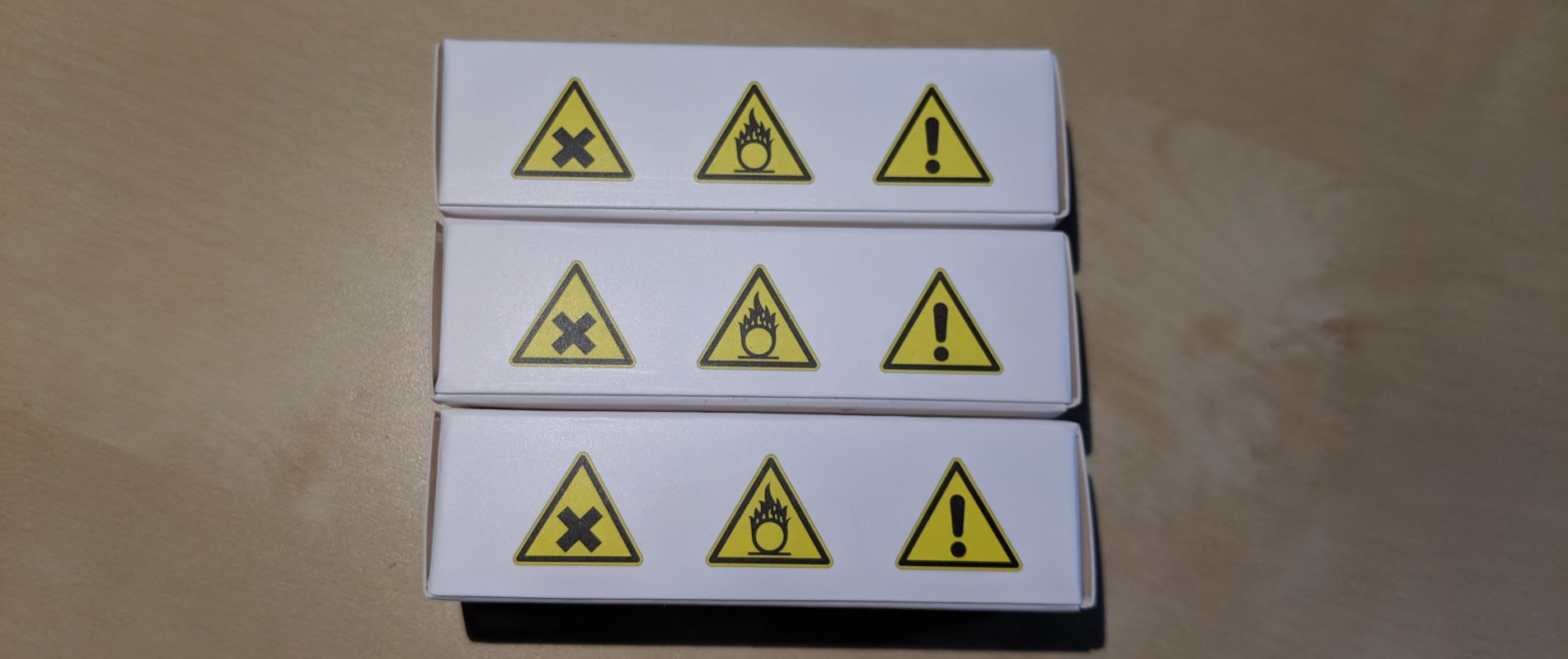
Caution: This powerbank contains nearly 100 Wh worth of LiIon cells. In normal operation, the (dis)charge PCB is in charge of battery management tasks like short circuit prevention. Disassembling the device exposes raw LiIon cells, which typically do not contain separate protection circuitry. Puncturing, shorting, or otherwise mishandling one of those can lead to fire. Don't disassemble a powerbank unless you know what you are doing.
Case Teardown
The top and bottom plastic covers are glued on and can be pried open with moderate effort, revealing four screws each.
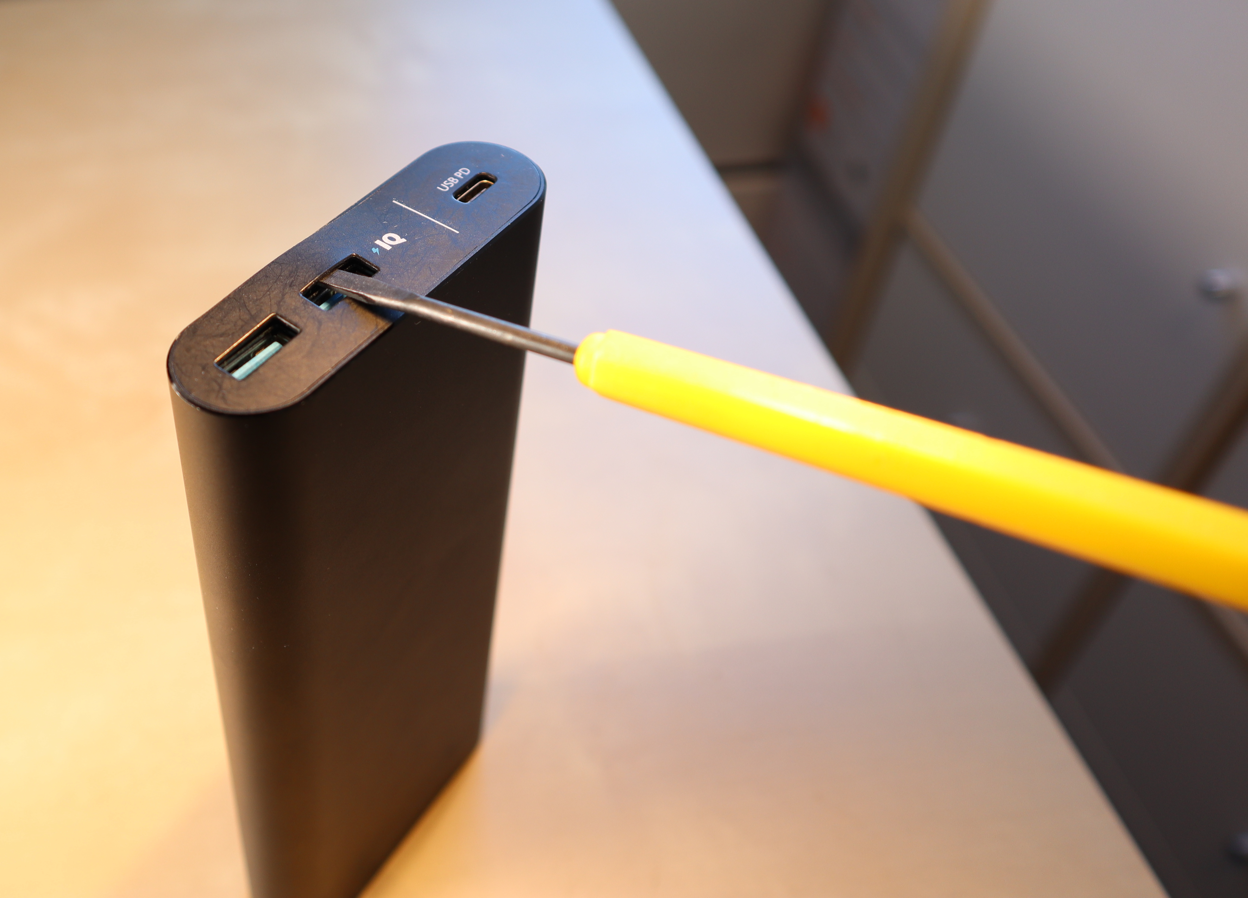

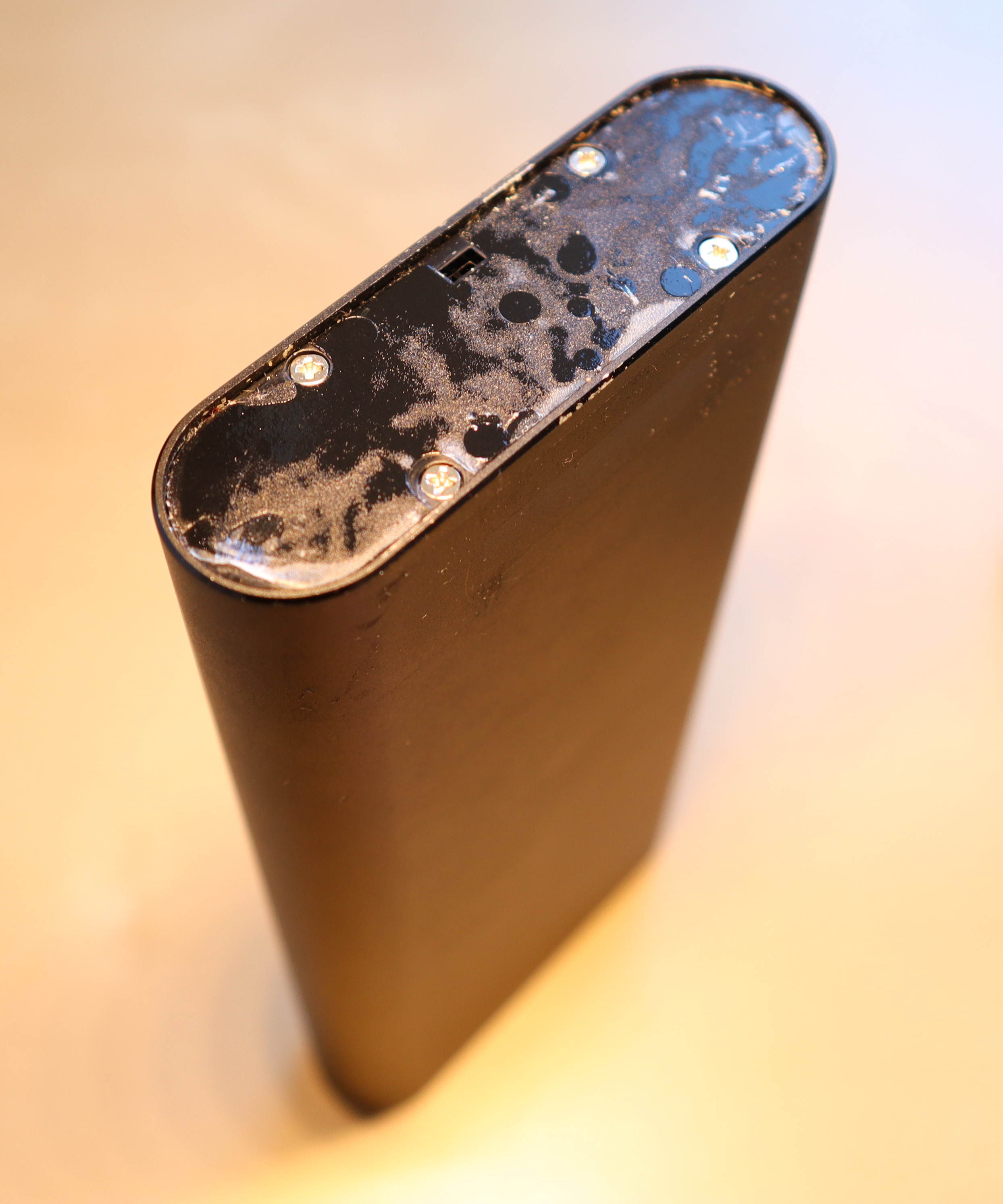
After removing the screws and a second (also glued-on) top cover, you can push onto the connector board (top) to coax the cell and PCB assembly out of the case. A good spot for application of force is the plastic surface next to the USB-C port. It's a tight fit, so the assembly won't slide out by itself. Pushing from the bottom won't work.

The LiIon cell layout is 2S4P with balancing. The cells are labeled “LGGBF1L1865”, which appears to correspond to LG's INR18650F1L model.
Each cell is rated as follows:
- Nominal capacity: 3.3 Ah at 3.63 V (12 Wh)
- Charge current: 0.3C (975 mA) nominal, 0.5C (1625 mA) maximum, 4.2 V / 50 mA cut-off
- Discharge current: 0.2C (650 mA) nominal, up to 1.5C (4875 mA) maximum, 2.5V cut-off
For the 2S4P pack, this gives:
- Nominal capacity: 13.2 Ah at 7.26 V (96 Wh)
- Charge current: 0.3C (3.9 A) nominal, 0.5C (6.5 A) maximum, 200mA cut-off
- Discharge current: 0.2C (2.6 A) nominal, up to 1.5C (19.5 A) maximum, 5.0V cut-off
For comparison, the powerbank's product specifications state:
- Capacity: 26.8 Ah at 3.6V (96 Wh)
- Input: Up to 27 W (9 V, 3 A) → Charging probably uses less than 0.3C
- Output: Up to 25 W (20 V, 1.25 A) via USB-C + about 20 W (5 V, 2 A) via USB-A → Discharge current is up to 0.5C (6.6 A)
My mostly discharged cells read 3.18 and 3.20V, respectively, so the cell management chip seems to be operating in a rather conservative voltage range. This should be good for longevity.


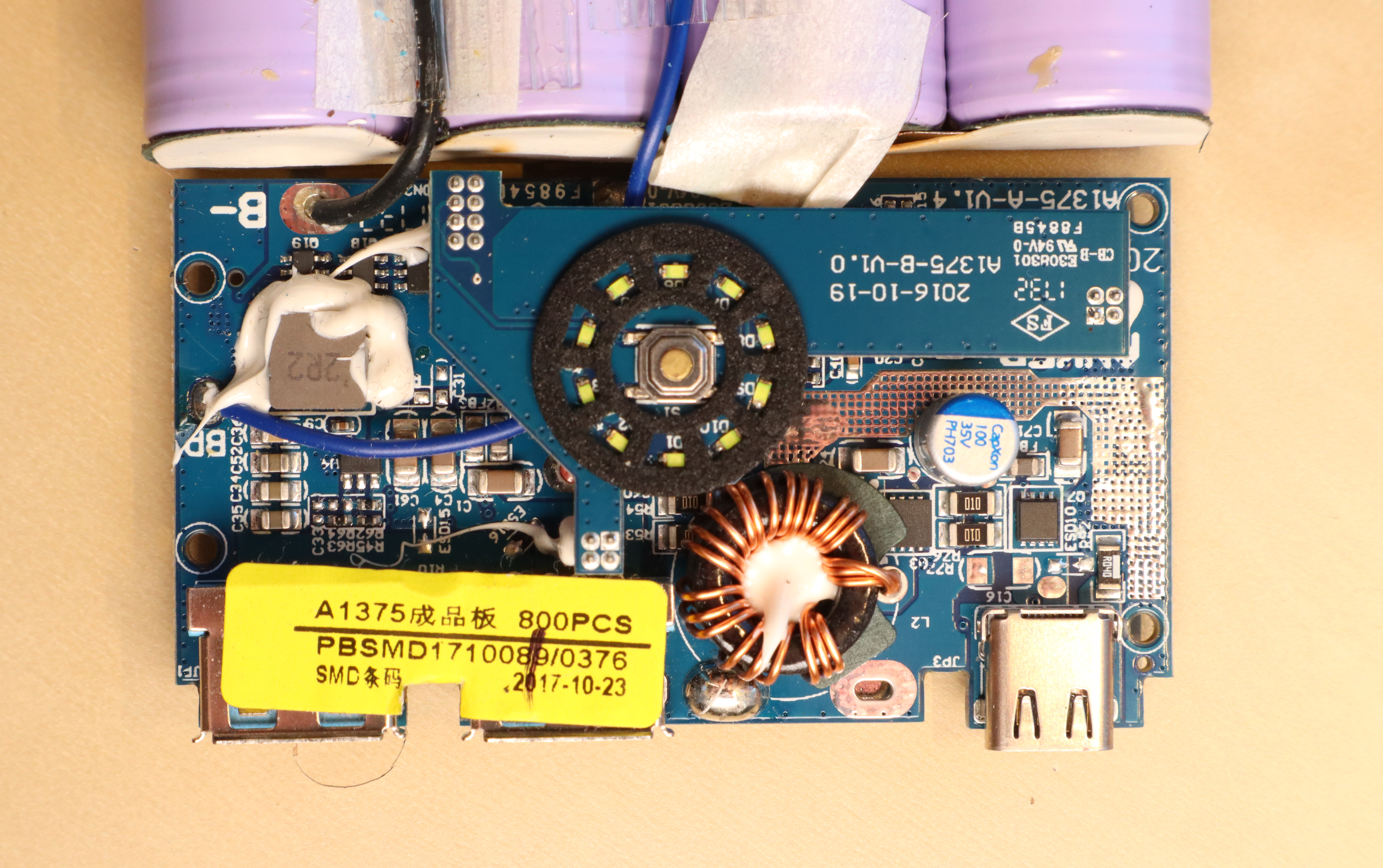
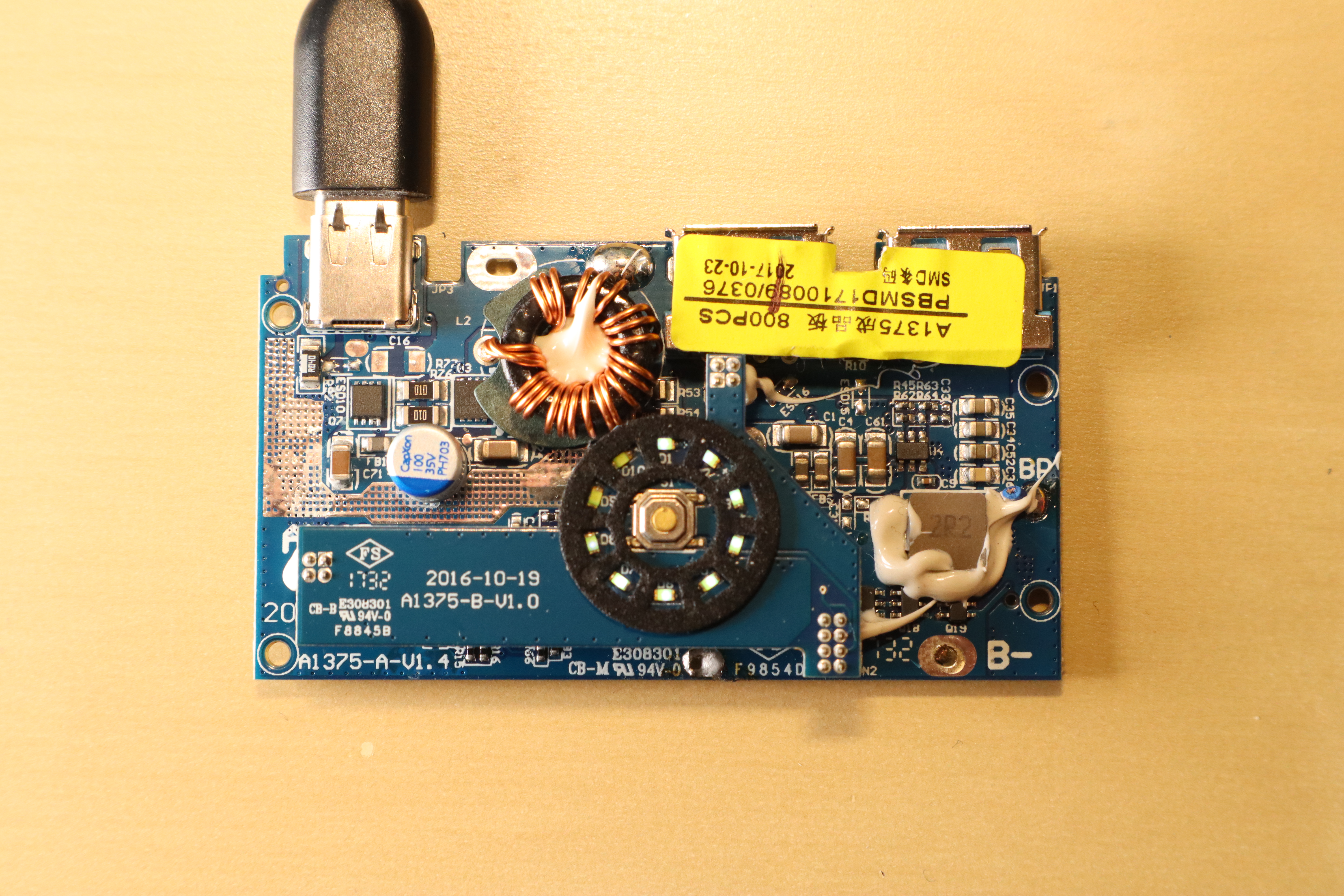
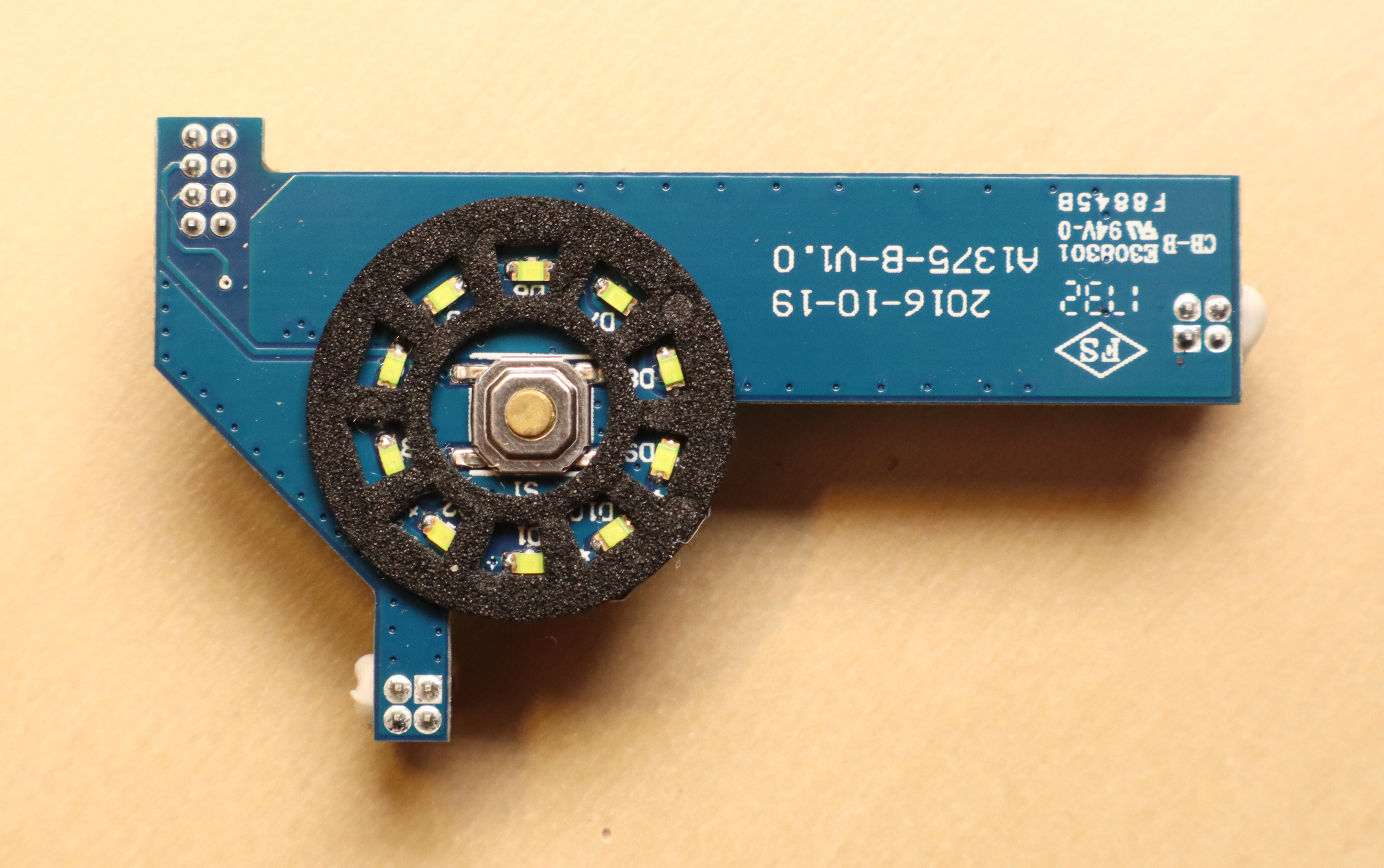
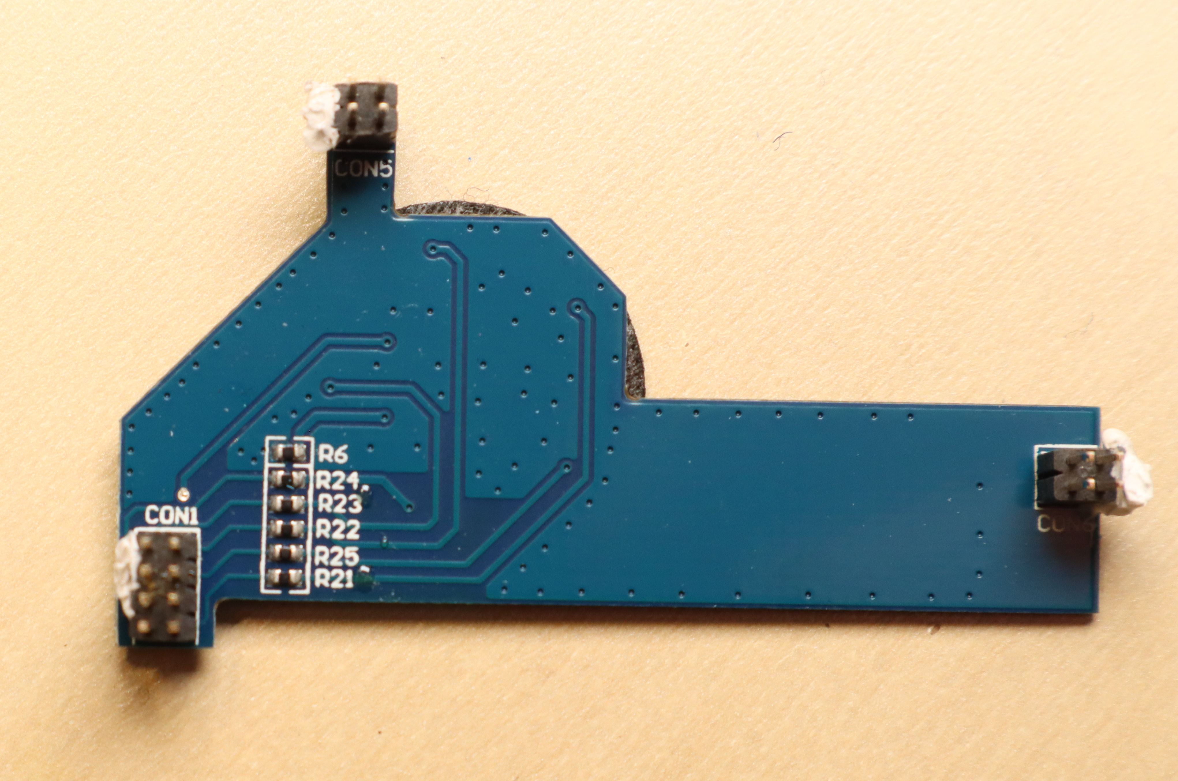
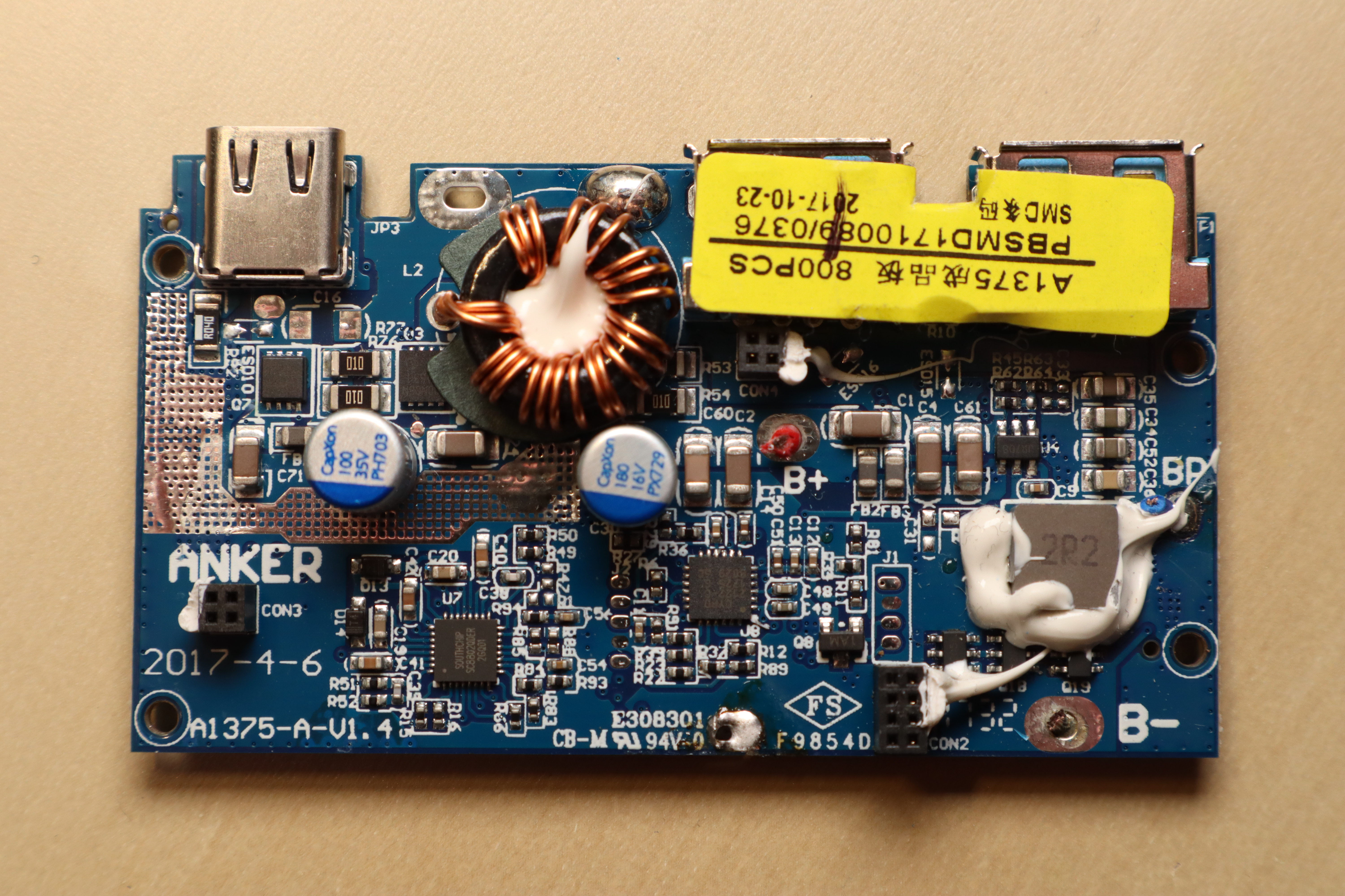
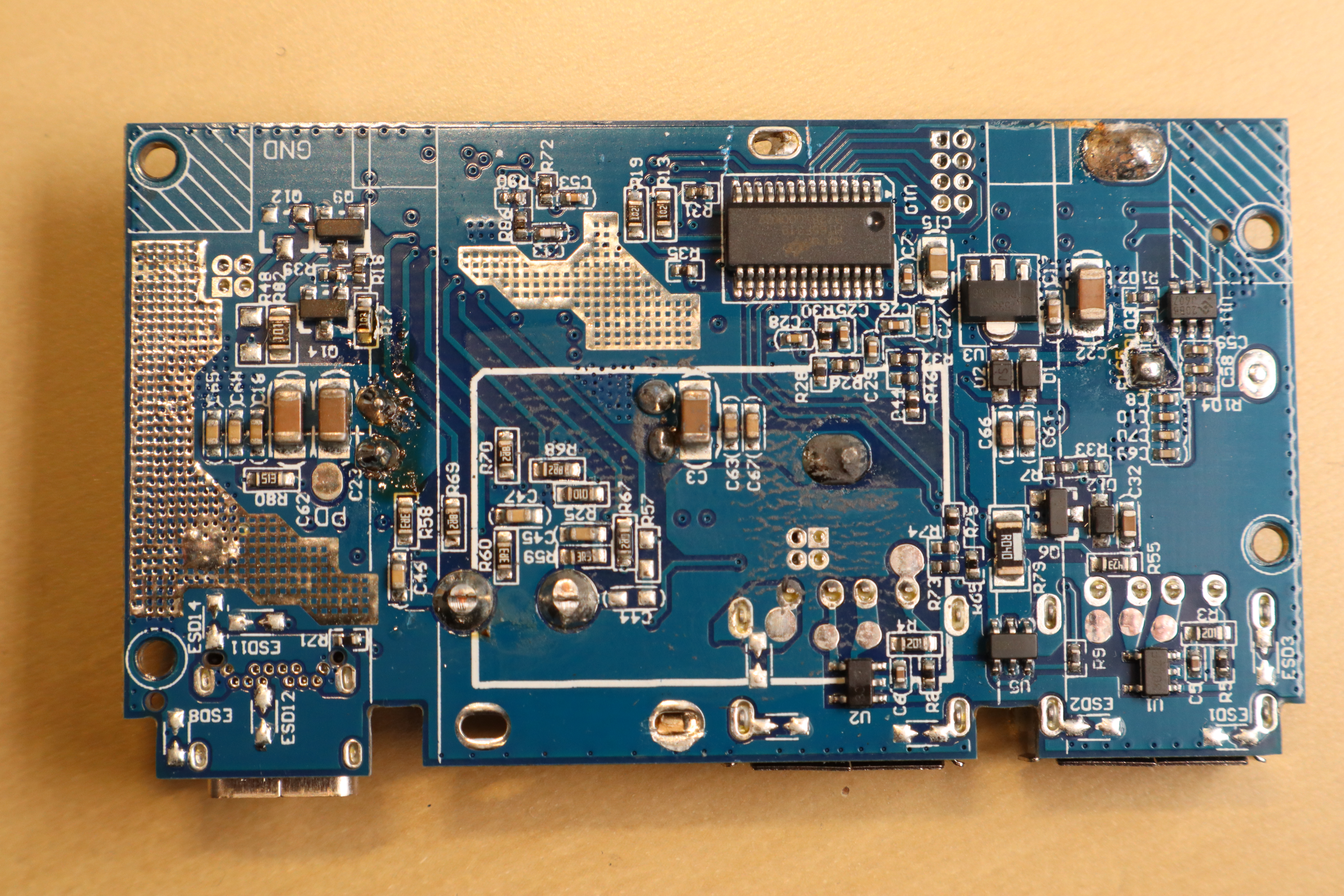
PCB Teardown
The top PCB is only responsible for LED output and button input.
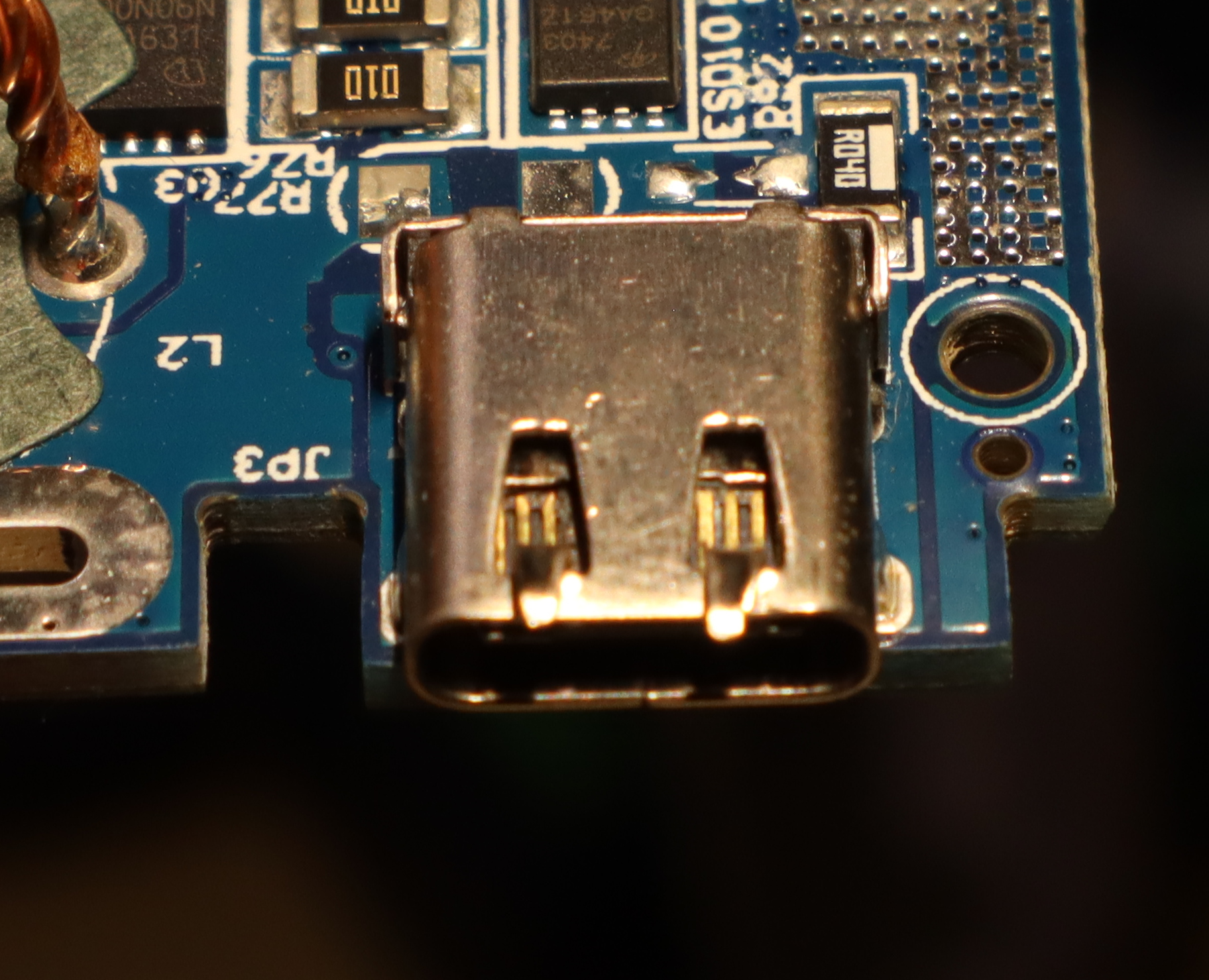
The bottom PCB includes an SC8802 synchronous, bi-directional, 4-switch buck-boost charger controller and a HT66F319 microcontroller.
The Culprit
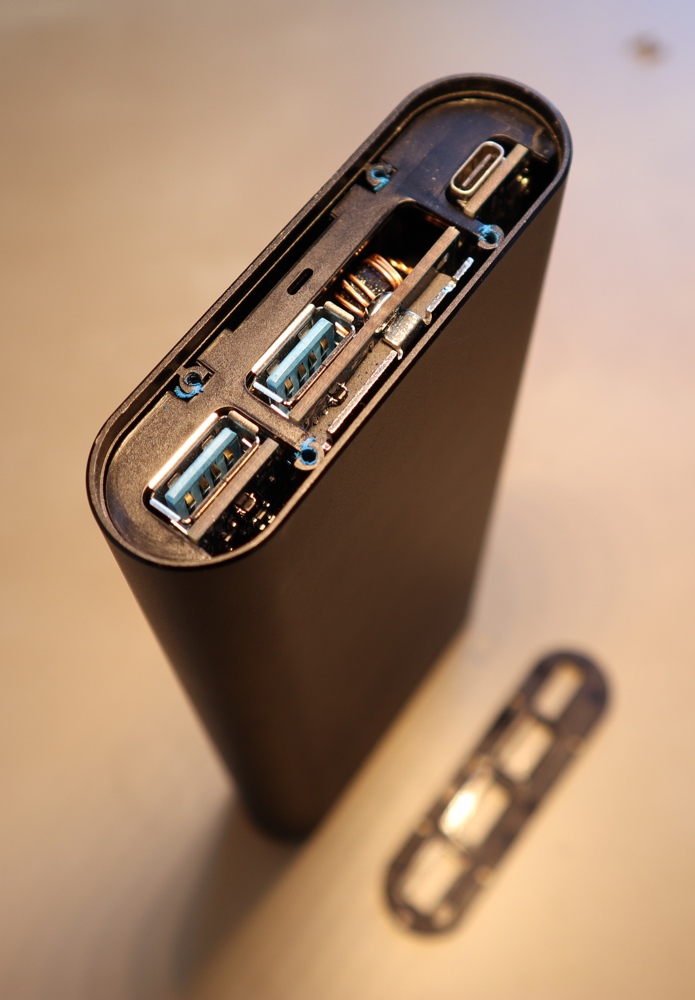
Even with disconnected batteries, there's a two ohm short circuit between USB-C VCC and USB-C GND. The culprit turned out to be the USB-C plug itself.
USB-C plugs contain a tiny PCB with contacts on both sides that the cable slides onto. In this case, the lower (recessed, non-contact) part of the PCB is embedded into a metal piece for stability. Over time, the metal piece had moved towards the contacts, eventually causing an electrical connection and thus a short circuit. After moving it back, the power bank is working again. I don't trust the USB-C port anymore, though.