Archives: 2010 2011 2012 2013 2014 2016 2017 2018 2019 2020 2021 2022 2023 2024 2025
Software-Defined FM Audio Transmission with ADI / PlutoSDR
ADI / PlutoSDR / PySDR are powerful tools for transmitting IQ samples. Here's how to transmit FM data with them, which can then be received, e.g., via a ham radio handset. I'll also try to explain how the whole transmission business works – however, my understanding of high frequency data transmission witchery is not that good (yet), so you'd better double-check anything you find here.
![]()
Note that emitting FM transmissions may be considered illegal depending on your jurisdiction, TX power, EIRP, and/or frequency band. This example is going to use the ham radio band, which requires you to have a license and mention your callsign in transmissions in all countries that I am aware of.
No lawyers or regulators were harmed in the making of this blog post (I do have a valid ham radio license and call sign. DF7LUX meowing here!).
Software Setup
See the pysdr.org documentation for a detailed how-to. In my case (Debian unstable), installing the required dependencies (libad9361-dev, libaio-dev), activating a Python3 virtualenv, and running the following commands within it was sufficient.
git clone --branch v0.0.14 https://github.com/analogdevicesinc/pyadi-iio.git
cd pyadi-iio
pip3 install --upgrade pip
pip3 install -r requirements.txt
pip install setuptools scipy
python3 setup.py install
Basics
PySDR / PlutoSDR works with IQ samples and applies them to a carrier frequency by itself.
Its tx function takes a bunch of samples and blocks until they have been transmitted.
First, we need to define some basic parameters.
Here, we're going to use 100,000 samples per tx call and a 1 MHz PySDR sample rate.
Our FM transmission will use a maximum deviation of 12.5 kHz, which seems to work best for my Radioddity GD77.
We're also going to use the ham radio 144.6 MHz band for this test.
n_samples_per_tx = 100_000
sdr_sample_rate = 1_000_000
fm_deviation = 12_500
fm_carrier = 144_600_000
Now, in order to get started, we need to import some modules:
import adi
import numpy as np
import time
import scipy.io
import scipy.signal
Reading in a WAV file
Given a 16-bit signed WAV file, we can use scipy.io.wavfile to load it.
wav_sample_rate, data = scpiy.io.wavfile.read("some audio that includes your callsign.wav")
We're going to do a simple mono transmission, so in case the file holds stereo data, we'll throw away the second channel:
len(data.shape) == 2:
    data = data[:, 0]
The WAV file holds 16-bit signed data (-32767 to 32768), whereas PySDR expects its samples to be 15-bit signed (-16383 to 16384) and the operations we're going to perform later assume floating point data in the range -1 to 1. Hence, we scale all samples to be within [-1, 1].
data = data / 2**15
Resampling
WAV files typically have a sample rate of 44.1 or 48 kHz; our SDR expects 1 MHz. So, for every sample in the WAV file, we must pass (roughly) 20 samples to the SDR.
We can use scipy.signal.resample to perform this transformation:
we have data.shape[0] input samples and must stretch the number of samples by the ratio of SDR sample rate to WAV sample rate.
samples = scipy.signal.resample(
    data, int(data.shape[0] * (sdr_sample_rate / wav_sample_rate))
)
Note: this function seems to be quite memory-hungry. Alternatively, you can try the following snippet, which is not how it should be done but seems to be work well enough in practice.
# samples = np.repeat(data, sdr_sample_rate // wav_sample_rate)
Low-Pass Filter
The Nyquist-Shannon theorem states that a receiver operating with a specific sampling rate f can only reconstruct signals with frequencies of up to f/2 correctly. Any higher transmitted frequencies may cause aliasing, which may or may not cause unwanted effects for audio data.
As far as I understand it, this does not quite apply to FM transmissions – we've got 12.5 kHz FM deviation, but the SDR's sample rate, and thus the available bandwidth, is 1 MHz – or something between those two frequencies, anyway. In any case, applying a digital filter that throws away anything abore 12.5 kHz (and below 20 Hz for good measure) won't hurt. I'm not familiar with the intricacies of scipy.signal yet – this Finite Impulse Response filter works, but is copy-pasted and adjusted based on best guesses. So you might want to do your own research here.
bb = scipy.signal.firwin(41, (20, fm_deviation), pass_zero=False, fs=sdr_sample_rate)
samples = scipy.signal.lfilter(bb, [1], samples)
scipy.signal offers lots of different filtering methods; there may be better / more elegant ways of low-pass filtering.
Interlude: AM Transmission
Our audio signal is now almost ready for transmission. In fact, if all we wanted to do is AM (amplitude modulation), we would already be done. Our SDR uses IQ sampling, which means that each sample consists of two component: I (multiplied with the cosine of the carrier frequency) and Q (multiplied with the sine of the carrier frequency). The actual transmitted signal is x(t) = I · cos(2πft) + Q · sin(2πft), with I and Q belonging to individual samples in the TX buffer and f being the carrier frequency. With a sample rate of 1 MHz and a carrier of 144.6 MHz, each sample is used for 144.6 periods of the underlying carrier's sine / cosine waves.
In PySDR, IQ samples are represented as complex numbers I + jQ, where I is the real part and Q the imaginary one.
As samples contains purely real values, we obtain x(t) = I · cos(2πft), meaning that our samples I are modulating the amplitude of the carrier frequency -- or, in short, we're doing AM.
Generating IQ Samples for FM Transmission
In order to do FM, we must adjust the frequency of the carrier rather than its amplitude – the amplitude should always remain at its maximum value.
So, if samples[i] == -1, we want to shift the carrier down by -12.5 kHz to transmit a 144.5875 MHz signal.
If samples[i] == 0, we want to leave it as-is (144.600 MHz), and for samples[i] == 1, we want to shift it by +12.5 kHz to end up at 144.6125 MHz.
With IQ sampling, we can control only two aspects of the 144.6 MHz carrier transmitted by the SDR: its amplitude (see above) and its phase. We cannot adjust the frequency directly. However, we can control the phase for each sample separately.
If we transmit two consecutive samples with a different phase, this will affect the carrier's sine wave right at the transition between the two samples. For a positive phase difference, the sine will be slightly “too slow”, i.e., essentially have a lower frequency than the configured carrier. For a negative phase difference, the sine will be slightly “too fast”, i.e., essentially have a higher frequency than the configured carrier. This is called phase modulation, and the nice thing about it is that it can also be used for frequency modulation.
Interlude: Frequency Modulation via Phase Modulaton
Let's assume that we had an SDR sample rate that is identical to the carrier frequency, so, 144.6 MHz. Each sample is precisely as long as a single period of the carrier signal.
If we shift the phase by 180° after each period of the carrier signal, this effectively increases the frequency of the transmitted sine wave by 50% – so, rather than a 144.6 MHz signal, we'll be transmitting a 216.9 MHz one. We'll also be transmitting a (smaller?) frequency component that is 50% slower than our carrier, so, at 72.3 MHz.
If we shift the phase by 90°, we increase (or decrease, depending on direction) the frequency of the transmitted sine wave by 25%, yielding 108.45 or 180.75 MHz. In general, if we shift the phase by φ°, we'll transmit 144.6 MHz + (φ/360°) · 144.6 MHz.
Now, with the SDR, we cannot shift the phase after each period of the carrier – we can only do so every few dozen to hundreds of carrier periods. In this specific case, with 144.6 MHz carrier and 1 MHz sample rate, we can shift the phase every 144-odd carrier periods.
Even in this case, frequency modulation via phase moulation still works. Let's say that we shift the phase every ten carrier periods for now. Now, we're only doing this “± 50%” dance on 10% of all periods, and, as luck would have it, that also means that our frequency deviation is just 10% as high: we get 5% shift of the carrier frequency rather than the 50% we had before. So, a 180° shift will cause the frequency spectrum to split into two peaks: one is 5% higher and one 5% lower, i.e., one at 137.37 MHz and one at 151.83 MHz. A 90° shift will cause the frequency to increase / decrease by 2.5%, and so on.
Generally speaking: A phase shift of φ° every n carrier periods will cause the transmitted frequency to change by (φ/360°) · (1/n) · 144.6 MHz.
And even more generally speaking, since n = carrierFrequency / sampleRate: A phase shift of φ° will cause the transmitted frequency to change by (φ/360°) · (1/(carrierFrequency/sampleRate)) · carrier, which simplifies to (φ/360°) · sampleRate.
FM Transmission
Now all that's left is determining the correct amount of phase change for each audio sample. At 1 MHz sample rate, the maximum we could do (with 180°, independent of carrier frequency) is ± 500 kHz, and we only need ± 12.5 kHz – so, the maximum required phase change is ± 4.5°.
We can also calculate that directly:
- deviation = (φ/360°) · sampleRate
- ⇒ φ = 360° · deviation / sampleRate
- ⇒ φ = 360° · 12.5 kHz / 1 MHz
- ⇒ φ = 4.5°
If we convert to radians (i.e., normalize 180° to π, which is how PySDR likes it), that's x = 2π · deviation / sampleRate.
At this point, there is one thing which I still do not understand: my code only works with x = π · deviation / sampleRate (note the missing factor of two). I suppose that I have simply mis-assumed the frequency deviation and should have used 6 kHz instead, but for now, I'm gonna leave this as-is. Let me know if you know more ^.^
So, what we finally have is:
phase_changes = samples * np.pi * fm_deviation / sdr_sample_rate
PySDR takes in absolute phase information, so we need to calculate the cumulative sum of this phase change array:
phase_integral = np.cumsum(phase_changes)
And with that, we can tell PySDR that we'd like to transmit a PM signal with a constant amplitude (of 1) and phases as determined by phase_integral:
fm_samples = np.exp(1j * phase_integral)
Boiler Plate
Now all that's left is scaling everything up from -1 … 1 to the 15-bit signed values that PlutoSDR expects, and then transmitting those.
fm_samples *= 2**14

sdr = adi.Pluto("ip:…")

sdr.sample_rate = int(sdr_sample_rate)
sdr.tx_rf_bandwidth = int(sdr_sample_rate)
sdr.tx_lo = int(fm_carrier)
sdr.tx_hardwaregain_chan0 = -10

print("SDR is being configured, waiting 2 seconds before beginning transmission …")
time.sleep(2)

for i in range(fm_samples.shape[0] // n_samples_per_tx):
    sdr.tx(fm_samples[i * n_samples_per_tx : (i + 1) * n_samples_per_tx])
The full script (with some quality-of-life improvements) is available at plutosdr-playground/tx-fm.py. Next item on the todo list is probably using multiprocessing so that the transmission can already start as the input file is being processed.
Automatic Screen Rotation on a Chuwi Minibook X
I recently got myself a new laptop (yes, in 2026, of all times – but at 360€, I'd say the price was quite acceptable): a Chuwi Minibook X. Performance-wise, it's nothing to write home about – it's slightly faster than the X270 I've been using since 2017, and I don't need any more than that. However, with a 10.5" Full HD touchscreen that supports 360° rotation, it's a really nifty netbook / tablet hybrid, and pretty much exactly the type of device that I've been looking for. Especially for hiking and related trips, I like having a laptop with me to pass the time on the train, but a 13.5" laptop was just too unwieldy for that.
When running the Minibook X with Gnome or similar environments, orientation-dependent screen rotation etc. should just happen automatically. In my case, I'm running i3, so I need to do that on my own. And, even if you don't want automatic rotation, you do need to make some changes at least once after booting: the netbook is using a tablet screen, and thus its native orientation is portrait mode.
Boot-Time Screen Orientation
Add the following parameter to the kernel command line (e.g., on Debian, by appending it to GRUB_CMDLINE_LINUX_DEFAULT in /etc/default/grub):
video=DSI-1:panel_orientation=right_side_up
Reading Out the Screen Angle
The netbook contains two identical accelerometers, one in the screen and one in the base. By default, Linux only exposes the one in the screen. There are ways around that, but in my case, a screen-only solution is sufficient.
So: /sys/bus/i2c/drivers/mxc4005/i2c-MDA6655:00/iio:device0/in_accel_?_raw contains raw readings in x, y, and z direction, depending on what you substitute for ?.
You could do some fancy trigonometry now, or you could just use the simplest heuristic that you can come up with.
I opted for the latter:
def get_accel(axis):
    with open(
        f"/sys/bus/i2c/drivers/mxc4005/i2c-MDA6655:00/iio:device0/in_accel_{axis}_raw",
        "r",
    ) as f:
        x = int(f.read())
    return x


if __name__ == "__main__":
    while True:
        x = get_accel("x")
        y = get_accel("y")
        if x < -500 and mode != "up":
            new_mode = "up"
            # The screen is in normal laptop orientation
        elif x > 500 and mode != "down":
            new_mode = "down"
            # The screen is in inverse laptop orientation ("tent mode")
        if y < -500 and mode != "normal":
            new_mode = "normal"
            # The screen is in its native orientation: it has been rotated into portrait mode so that the hinge is on the left when looking at the screen
        elif y > 500 and mode != "flip":
            new_mode = "flip"
            # The screen has been rotated into portrait mode so that the hinge is on the right when looking at the screen

        # ...

        time.sleep(1)
Changing Screen Orientation
Adjusting the screen orientation actually consists of two commands: one for output (xrandr, as usual), and one for touch input (xinput coordinate transformation matrix). Otherwise, touchscreen events will no longer map to the right display coordinates.
Laptop Configuration ("up")
xrandr --output DSI-1 --rotate rightxinput set-prop pointer:Goodix Capacitive TouchScreen --type=float Coordinate Transformation Matrix 0 1 0 -1 0 1 0 0 1
The second line sets the 3×3 coordinate transformation matrix to the following value:
 0  1  0
-1  0  1
 0  0  1
Tent Configuration ("down")
xrandr --output DSI-1 --rotate leftxinput set-prop pointer:Goodix Capacitive TouchScreen --type=float Coordinate Transformation Matrix 0 -1 1 1 0 0 0 0 1
The second line sets the 3×3 coordinate transformation matrix to the following value:
 0 -1  1
 1  0  0
 0  0  1
Tablet Configuration 1 ("normal")
xrandr --output DSI-1 --rotate normalxinput set-prop pointer:Goodix Capacitive TouchScreen --type=float Coordinate Transformation Matrix 1 0 0 0 1 0 0 0 1
The second line sets the 3×3 coordinate transformation matrix to the following value:
 1  0  0
 0  1  0
 0  0  1
Tablet Configuration 2 ("flip")
xrandr --output DSI-1 --rotate invertedxinput set-prop pointer:Goodix Capacitive TouchScreen --type=float Coordinate Transformation Matrix -1 0 1 0 -1 1 0 0 1
The second line sets the 3×3 coordinate transformation matrix to the following value:
-1  0  1
 0 -1  1
 0  0  1
Toggling Keyboard and Touchpad
Outside of laptop mode, I disable keyboard and touchpad so that I can actually use the device like a tablet.
Disabling Keyboard and Touchpad ("down", "normal", "flip")
xinput disable 'AT Translated Set 2 keyboard'xinput disable 'XXXX0000:05 0911:5288 Touchpad'
Enabling Keyboard and Touchpad ("normal")
xinput enable 'AT Translated Set 2 keyboard'xinput enable 'XXXX0000:05 0911:5288 Touchpad'
Setting the Wallpaper
After each rotation, you should set the wallpaper again to ensure that it is displayed correctly. How to do that depends on your setup – in my case, I'm using a simple wrapper around feh.
I have uploaded the full auto-rotate script at (sans custom wallpaper-setter) at chuwi-accel.py
Docker Multi-Platform Builds with a Remote Build Host
I finally got multi-platform / multi-arch Docker builds to work!
In principle, if you want to provide a single Docker image for both amd64 and arm64, all you need to do is run docker buildx build --platform linux/amd64,linux/arm64 ….
However, in order for this to actually work, there are several hoops to jump through.
The following how-to is mostly reconstructed from short-term memory and shell history, so you may want to double-check what I'm writing with the documentation.
Docker Storage Format
First, if you're using Docker version 28 or earlier, you need to change the storage format to one that supports multi-platform containers.
In my case, merging the following content into /etc/docker/daemon.json was sufficient:
{
  "features": {
    "containerd-snapshotter": true
  }
}
Not Recommended: binfmt / qemu
I first tried multi-platform builds by installing qemu-system-aarch64 and binfmt-support – in this case, Docker will use (slow!) software emulation for any selected, non-native platform.
However, I never got that to work – the non-native part would always fail at random places, and given its slow progress I was not very keen on debugging it.
Instead, I opted for a setup with two different, native build hosts: one for amd64 and one for arm64. In my case, I have an amd64 VM as the main build host, and an aarch64 / armv8 SoC as build host for arm64. I want to run all commands on the amd64 VM, and the arm64 host should be fully remote-controlled.
Adding Contexts and Builders
In order to make the amd64 VM aware of the arm64 build host, we need two aspects: a context and a builder.
docker context create raspi4 --docker 'host=ssh://user@host'
docker buildx create --use --name arm64_raspi4 --platform linux/arm64 raspi4
(adjust user and host according to your setup)
(Note: the second line may not be required if all you want / need is a single multi-platform builder – see below)
At this point, we can build either for amd64 or arm64, but not yet both at the same time.
If we tried to run docker buildx build --platform linux/amd64,linux/arm64 … now, it would fall back to software emulation via qemu for one of the two platforms, depending on which of the two builders (default / arm64_raspi4) is currently selected.
Note: In principle, you can also adjust the arm64 host's systemd docker invocation to include -H tcp://0.0.0.0:port, and then use --docker 'host=tcp://ip:port' when creating the context.
However, that will give anyone on the local network docker (and, thus, root) access to the arm64 host.
An SSH connection is a much better choice.
Adding a Multi-Platform Builder
Luckily, Docker has a concept of builders that consist of multiple endppoints:
docker buildx create --use --name multiarch default
docker buildx create --append --name multiarch raspi4
As docker buildx ls shows, we now have a builder that supports two sets of platforms:
NAME/NODE             DRIVER/ENDPOINT                   STATUS     BUILDKIT         PLATFORMS
multiarch*            docker-container
 \_ multiarch0         \_ unix:///var/run/docker.sock   running    v0.29.0          linux/amd64, linux/amd64/v2, linux/386
 \_ multiarch1         \_ raspi4                        running    v0.29.0          linux/arm64, linux/arm/v7, linux/arm/v6
And, as the asterisk indicates, it has been selected as builder for all subsequent docker commands. At this point, building works as intended. In my case, I'm using the following commandline to also tag and push the multi-platform image to docker hub:
docker buildx build --push --platform linux/amd64,linux/arm64 --tag derfnull/db-fakedisplay:${VERSION} --tag derfnull/db-fakedisplay:latest --build-arg=dbf_version=${VERSION} .
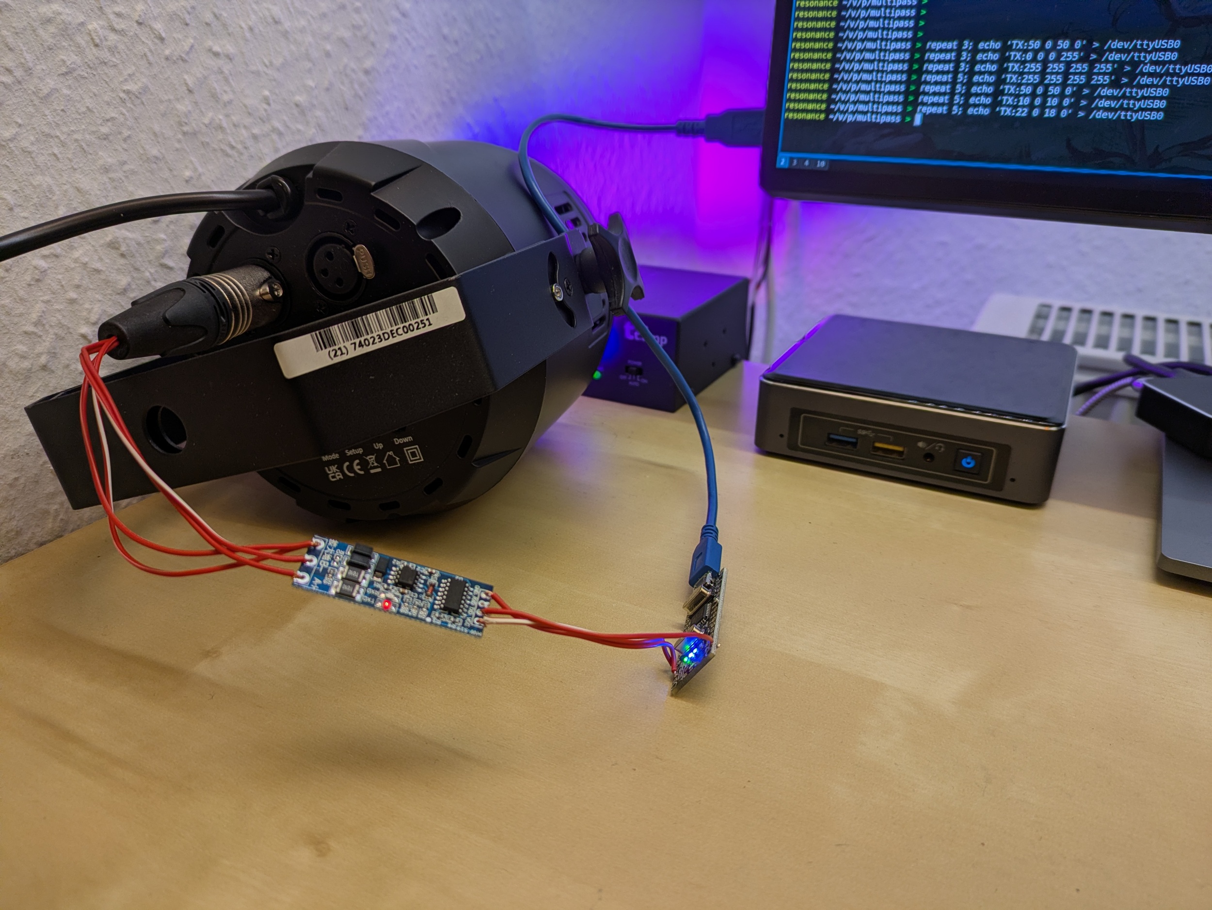
USB → DMX with a single UART (e.g. on an Arduino Nano)
Just in case you're as curious as I was: yes, you can absolutely build a USB to DMX converter that uses a single UART both for receiving ASCII DMX frames via USB (e.g. using an FT232 or CH340G chip) and for sending out DMX frames to a MAX485 or similar. Just not at the same time, but that's what we've got TDMA (time division multiple access) for.
Or, to use a concrete example: yes, an Arduino Nano (ATMega328P with USB-to-serial on-board) can be turned into a USB-to-DMX converter by adding an RS485 adapter and writing a bit of firmware.
The idea is quite simple:
- Every 250 or so milliseconds, disable the UART receive interrupt, configure the UART for DMX output (250 kbaud, 8 data bits, 2 stop bits, no parity), and transmit a DMX frame
- Once done, configure the UART for serial input (e.g., 57600 baud, 8 data bits, 1 stop bit, no parity) and enable the receive interrupt
- Once a complete DMX frame has been received on the USB side, update the DMX output frame accordingly
- Rinse and repeat, making sure not to output any serial data via UART – it's scrictly DMX only
The single drawback is that, while DMX output is running, UART input will be lost – there's no receive interrupt, and even if there was, it would be gibberish due to incompatible UART configuration. However, 57600 baud is not that fast compared to 250 kbaud, so if the PC just transmits its desired DMX frame a few times in quick succession, one of them is bound to be received.
I implemented this in multipass as uart-to-dmx-mega328 and so far it's working reliably. Of course, it's not suitable for anything where you need sub-second scale timing accuracy. But if all you need are some static or slowly fading background hues, it works just fine. In my case, the Neutrik XLR plug used to transmit the DMX signals to a light fixture is probably by far the most expensive item in the entire setup, save for the light fixture itself.
There's two noteworthy aspects:
Path Adjustments in libvirt / qemu
I'm running Home Assistant OS as a virtual machine on my home server. The HASS OS VM image relies on an OVMF file for booting; this file moved to a different path.
So, in order to make Home Assistant boot again after the upgrade to Debian 13, edit /etc/libvirt/qemu/hassos.xml (or similar) and change /usr/share/OVMF/OVMF_CODE.fd to /usr/share/OVMF/OVMF_CODE_4M.fd.
paho.mqtt.client changes
The upgrade from python3-paho-mqtt 1.6.1 to 2.1.0 came with some changes in its API.
In order to make it happy (and not spew any warnings), replace paho.mqtt.client.Client() with paho.mqtt.client.Client(callback_api_version=paho.mqtt.client.CallbackAPIVersion.VERSION2).
Apart from that, everything went smoothly.
Logging Steam Deck Hardware Stats to InfluxDB
I'm a sucker for colourful Grafana graphs (and not-necessarily-useful data logging in general), so naturally, I also had to see if I could get some hardware stats from my Steam Deck in there. Turns out: thanks to Deck's Linux foundation, this is quite easy. All you need to do is enable SSH access (or work directly on the device) and set up a systemd user timer with whatever kind of data logging you want. In my case, I did the following:
- Switch to desktop mode
- Open
konsole(i.e., the terminal app) - Run
passwdto set a password for thedeckuser ssh deck@steamdeckfrom my workstation- Install a script for InfluxDB logging in
~/bin - Install a user service and associated timer in
~/.config/systemd/userto run this script every few minutes - Enable the timer
My script looks as follows:
#!/bin/sh

HOST=steamdeck

exec curl -s -XPOST 'https://[…]/influxdb/write?db=hosts' \
--data "
memory,type=embedded,host=${HOST} $(free -b | awk '($1 == "Mem:") { printf "used_bytes=%d,used_percent=%f", $2 - $7, ($2 - $7) * 100 / $2 }')
$(awk '($1 ~ /^(.*):$/) { gsub(/:/, "", $1); printf "interface,type=embedded,host='${HOST}',name=%s rx_bytes=%d,rx_drop_count=%d,tx_bytes=%d,tx_drop_count=%d\n", $1, $2, $5, $10, $13 }' /proc/net/dev)
$(df -B1 | awk '($1 != "Filesystem") { gsub(/%/, "", $5); printf "filesystem,type=embedded,host='${HOST}',device=\"%s\",mountpoint=\"%s\" total_bytes=%d,used_bytes=%d,available_bytes=%d,used_percent=%d\n", $1, $6, $2, $3, $4, $5 }')
load,type=embedded,host=${HOST} $(awk '{print "avg1=" $1 ",avg5=" $2 ",avg15=" $3}' /proc/loadavg)
users,type=embedded,host=${HOST} $(who | awk '($5 !~ /tmux/) {logins++} END { printf "login_count=%d,session_count=%d", logins, NR }')
battery,type=embedded,host=${HOST},id=1 capacity_percent=$(cat /sys/class/power_supply/BAT1/capacity),cycle_count=$(cat /sys/class/power_supply/BAT1/cycle_count),voltage_uv=$(cat /sys/class/power_supply/BAT1/voltage_now)
$(for i in /sys/class/thermal/thermal_zone*; do test -r $i/type && test -r $i/temp && echo "sensor,type=embedded,host=${HOST},name=$(cat $i/type) mdegc=$(cat $i/temp)"; done)
"
This gives me stats about memory and disk (SSD + µSD) usage, load, and current battery charge and voltage. Unfortunately, power readings do not seem to be available.
For instance, the following screenshots show an evening DOOM session, followed by leaving the Deck idle to finish some downloads.

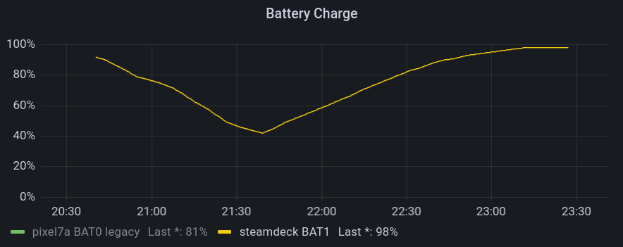

They allow for insights such as:
- The Steam Deck typically reaches 80°C when running hardware-intensive games
- Battery drain really depends a lot on what kind of game you're playing
- The Lenovo USB-C Slim Travel Dock I'm using for working at home works just fine with the Steam Deck, but fails to negotiate proper power delivery, so the battery slowly drains when playing.
EOS M50 Eyecup / Viewfinder Repair
Recently, I managed to drop my Canon EOS M50 while changing lenses. The fall wasn't that high (maybe 20cm, give or take), but exerted enough force on the body to dislodge the viewfinder's eyecup. This caused the viewfinder's proximity sensor to always detect something (namely, the eyecup's plastic), which, in turn, meant that the camera would no longer operate its 3" LCD – after all, someone was using the viewfinder, so better turn it off in order to save power.

Trying to shove the eyecup back into place did not work at all, and the fact that Canon does not treat it as user-serviceable or -replaceable did not bode too well. After a few weeks' worth of hesitation, I decided to try disassembling the camera up to the eyecup and repair / re-align it myself. It was long out of warranty, so at least I culd not void anything by trying my luck. There was just the risk of “verschlimmbessern” (making something worse by trying to improve), i.e., breaking the camera entirely when trying to repair it.
So, as usual: only do this if you know what you're doing, and don't blame me if something breaks.
Disassembly
Getting to the eyecup requires removal of nine (black, plastic?) PH0 screws and two parts of the camera's plastic shell. I did not check the screw types thoroughly – they all seemed quite similar, but I still made sure to re-apply each screw to the correct hole just to be on the safe side.
First, remove the microphone and NFC cover on the left. It is held in place by three screws, and can be carefully lifted out once they are loose. There are no plastic clips or anything, so you should not need to apply force.


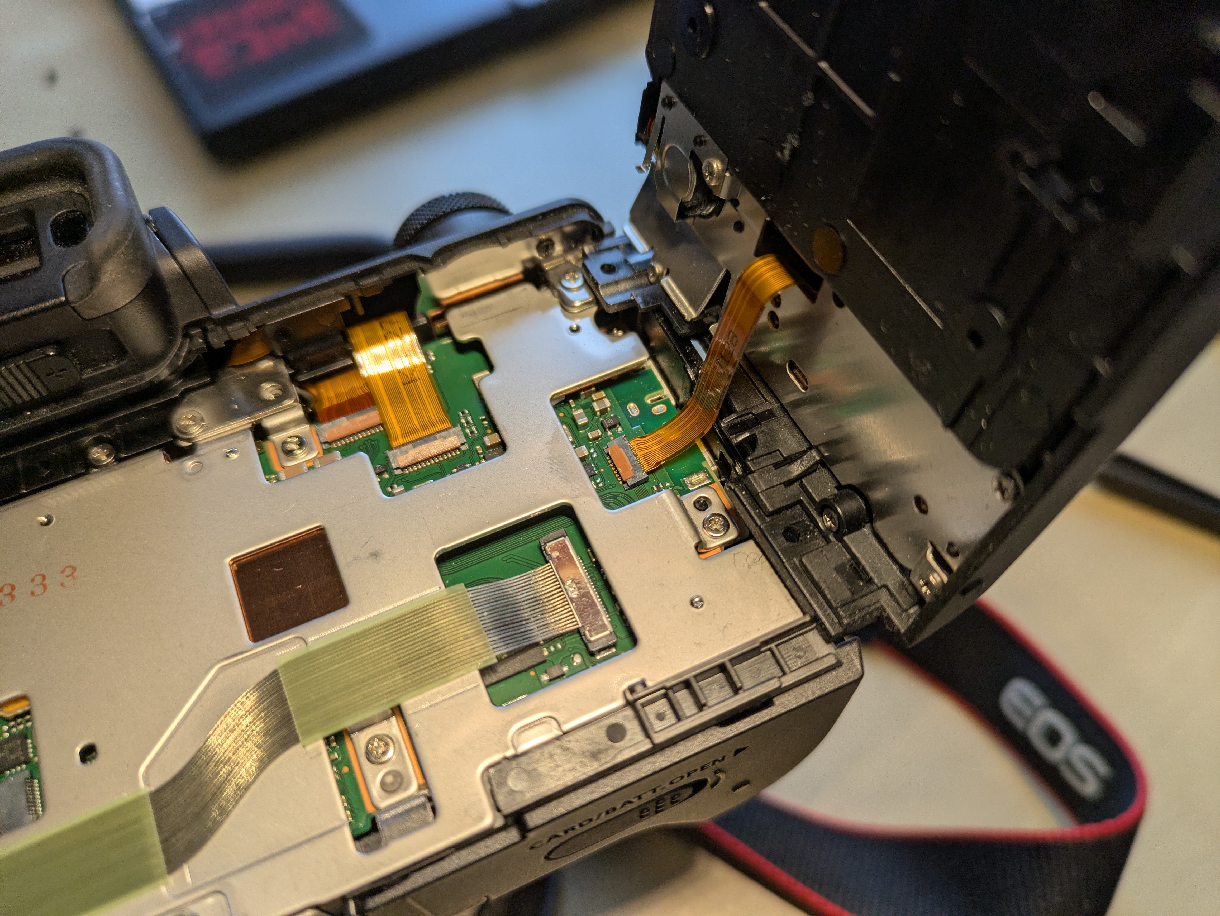
Then, flip out the 3" LCD so that it is out of the way and reveals two screws below the viewfinder. Remove these, the two screws at the tripod mount, and the two screws on the right side. The plastic part that you can now remove holds control button and is connected to the camera with a flat flex cable right below the control buttons. So, carefully fold out the plastic back (including the control buttons), and tilt it to the right to avoid stressing said cable. You only need to rotate it by about 90° in order to expose the final (tenth) screw securing the eyecup. You can choose between disconnecting it and storing it somewhere safe, or leaving it connected and being extra careful not to break it.


Repair
Now, remove the metal screw holding the eyecup. In my case, once the screw was out, I could easily move the eyecup back into place (without having to exert force) and was already done with the repair. I expect that you can also replace the entire eyecup at this point, but I did not try that.

Re-Assembly
- Secure the eyecup with the metal screw
- Reconnect the flat flex cable leading to the control buttons on the back cover
- Snap the back cover back into place. Do not secure it yet.
- Turn on the camera and verify that eyecup / viewfinder, 3" LCD, and the control buttons on the back (next to the LCD) are working
- Turn the camera off
- Secure the back cover with its six black screws
- Snap the side cover back into place
- Secure the side cover with its thre black screws
In my case, I did not verify that the control buttons are working before re-applying all screws. While I had not unplugged the flat flex cable, I had still managed to loosen its connector, so I had to go back and re-connected it in order to have a working camera again. Before proceeding with the re-assembly, the connector should look roughly like this:
Apart from that, this was a pleasantly straightforward repair, and definitely better than just not using the LCD anymore.

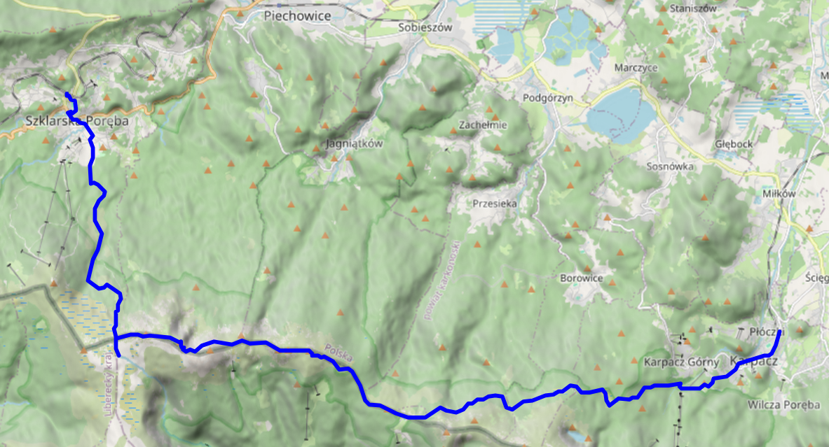
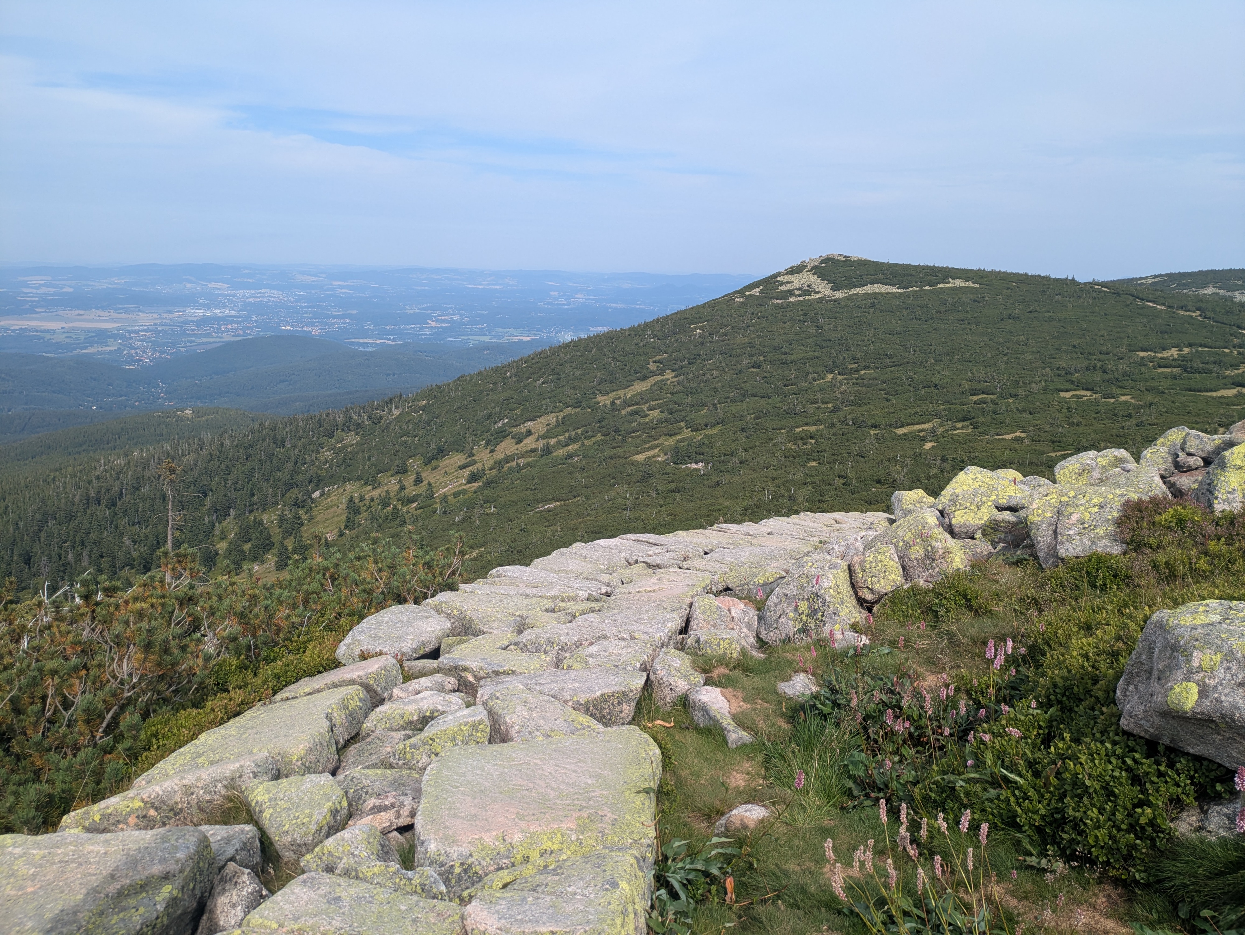
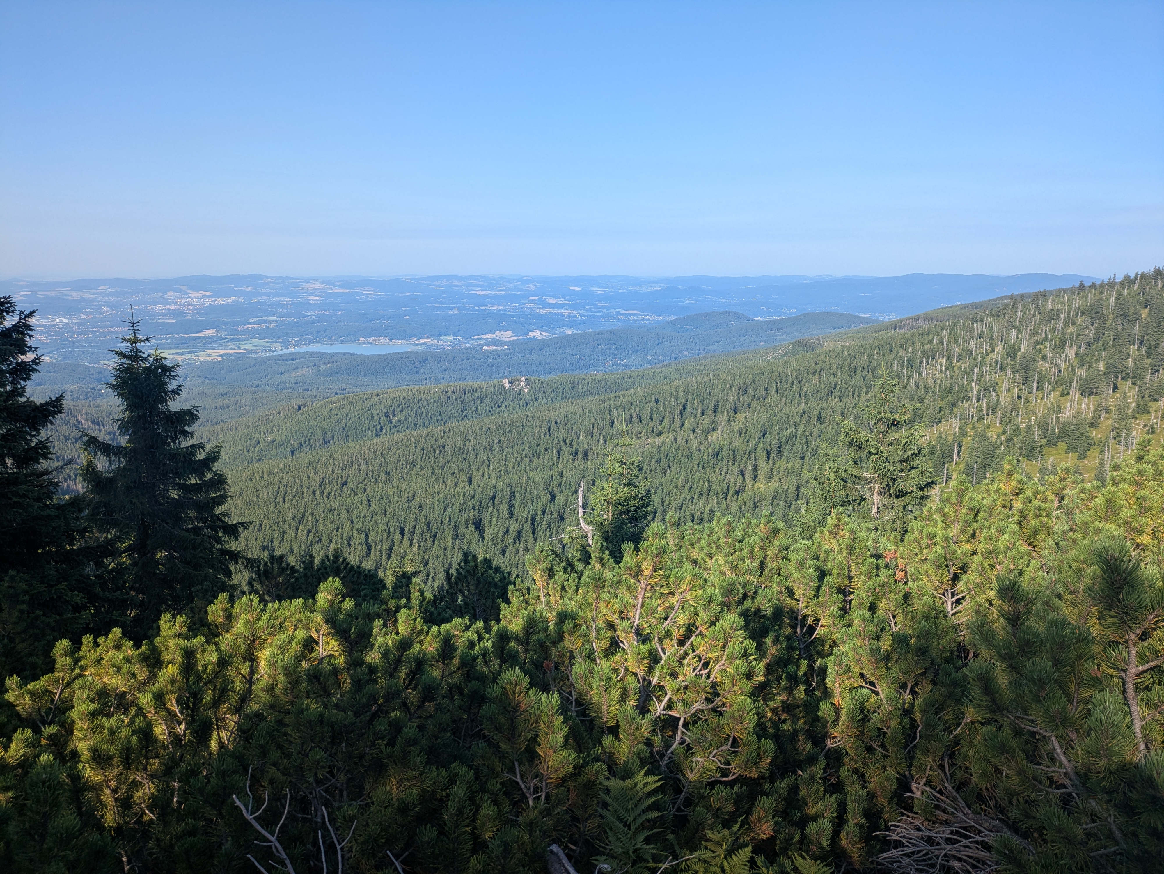
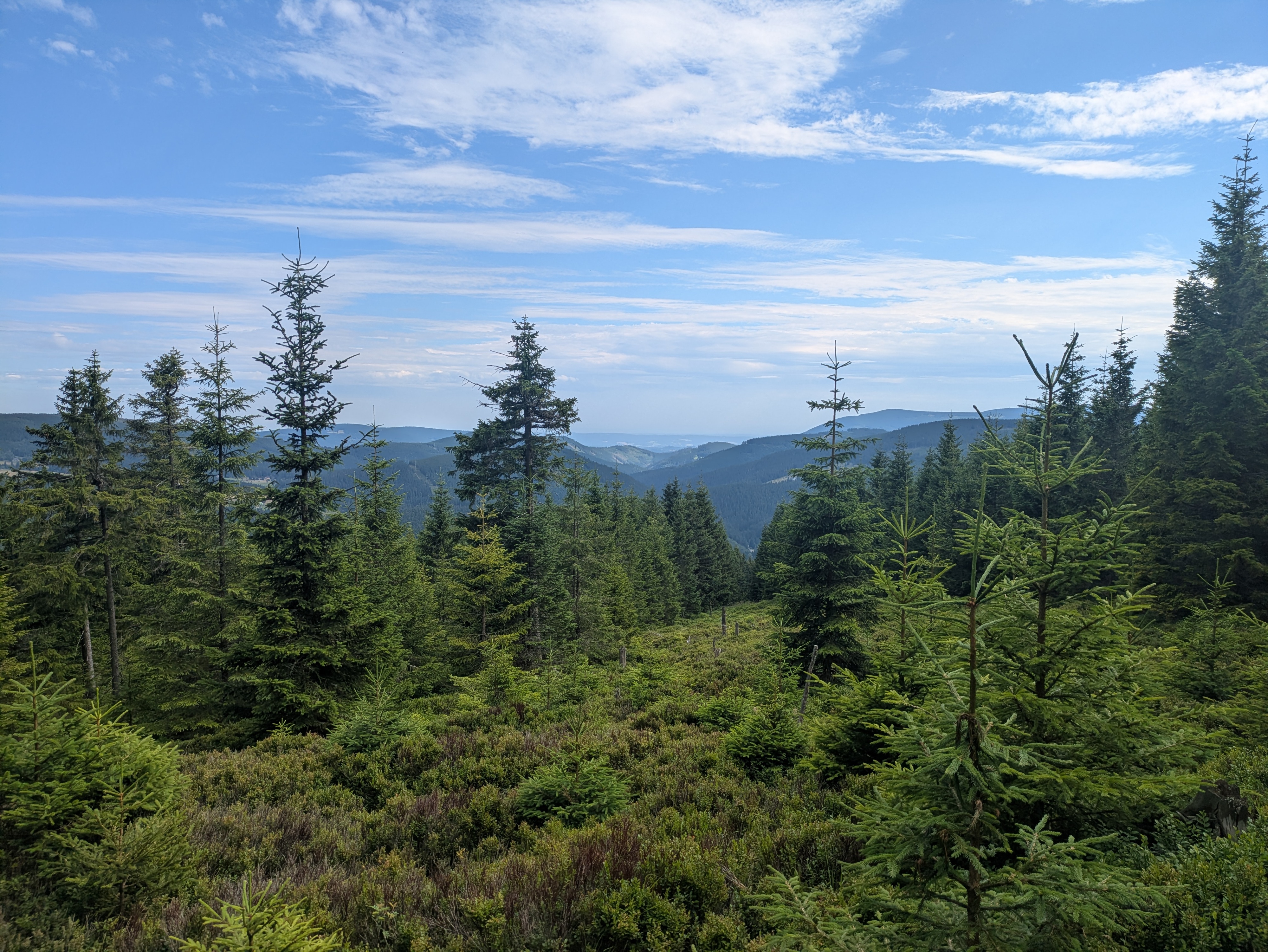
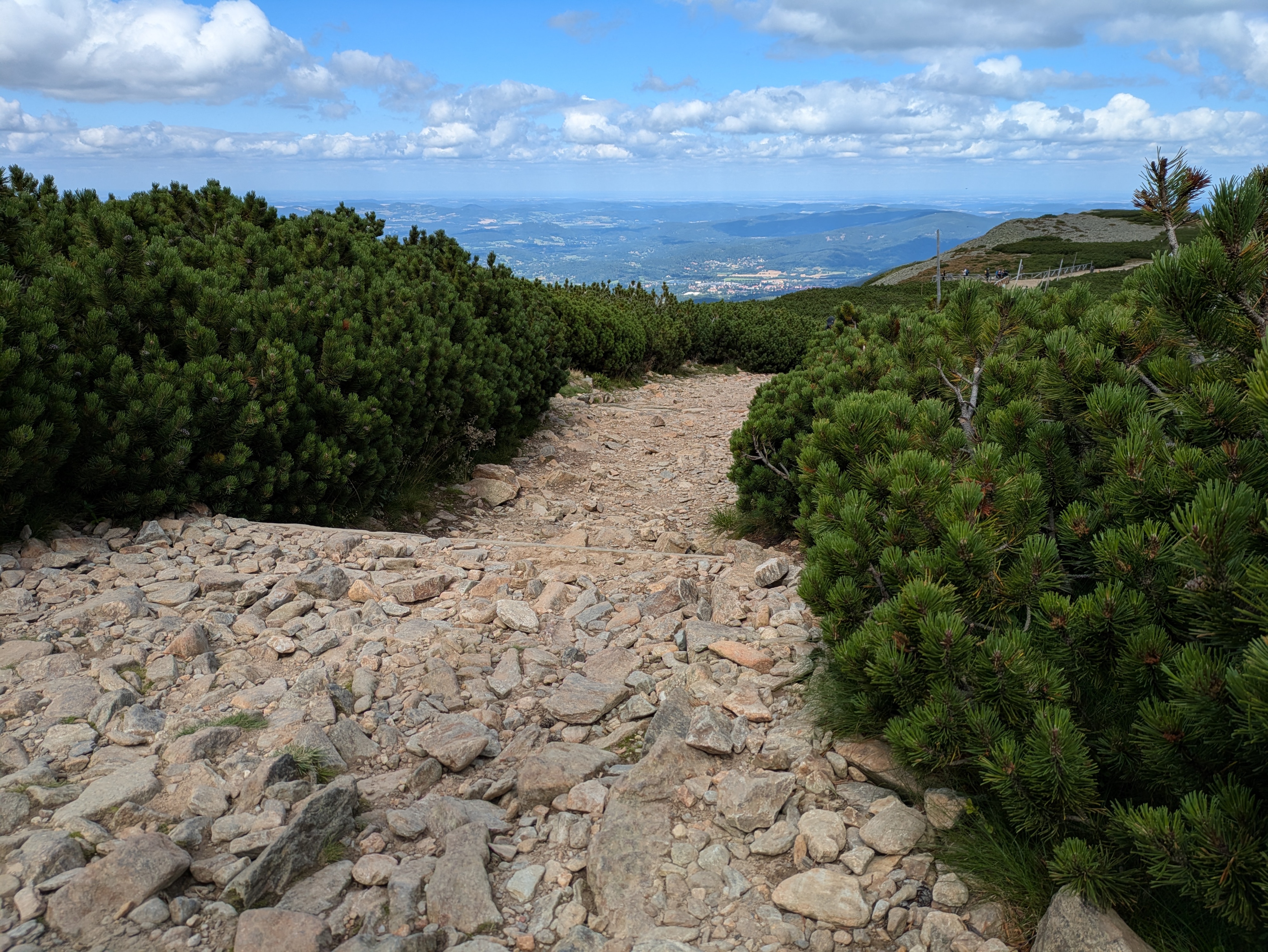
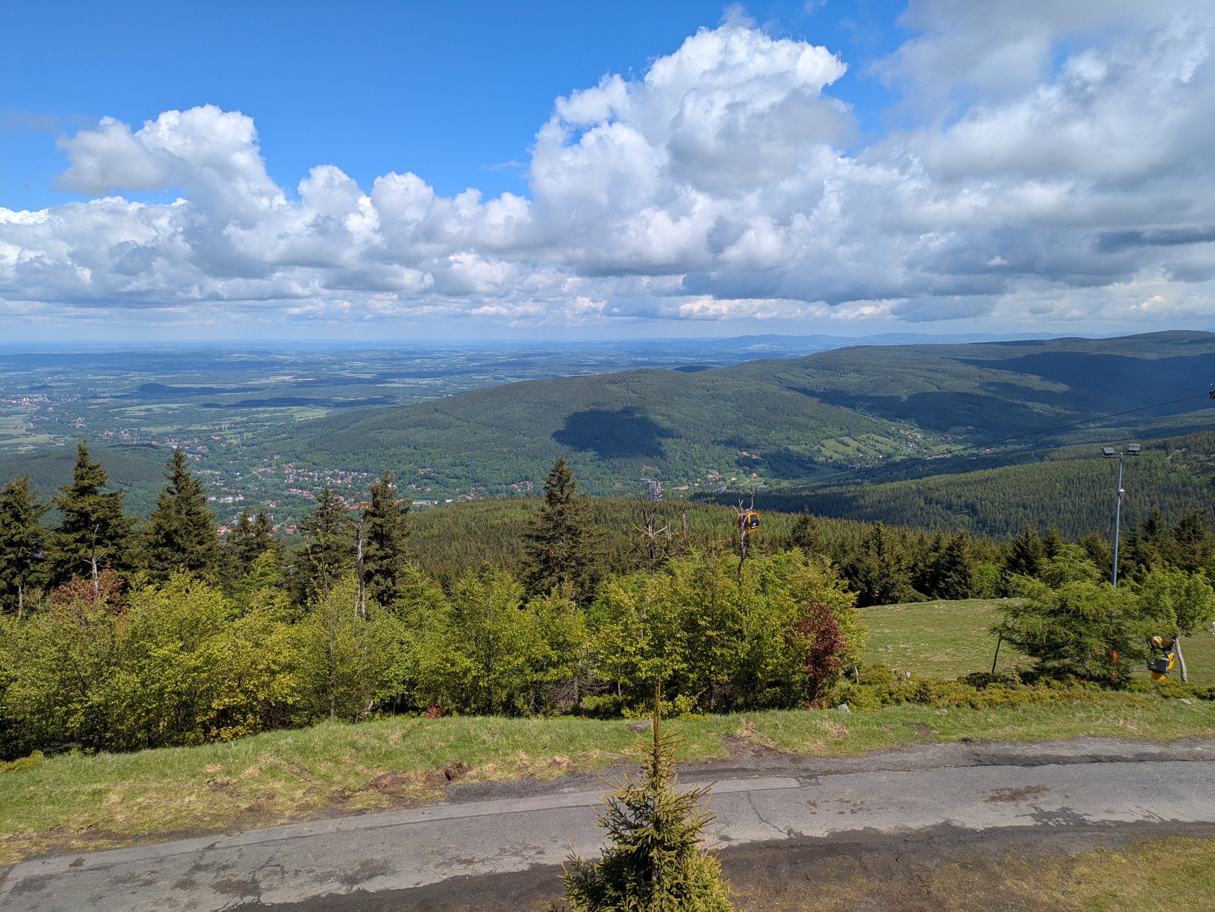
On the fourth and final full day of our vacation in the Giant Mountains, we decided to go for a change of scenery: take the train to Szklarska Poreba (Schreiberhau), walk up to Pramen Labe (Elbquelle / spring of the Elbe river), and then, depending on time of day and our appetite for more, either take the train back to Karpacz or walk back there across the peaks of the Giant Mountains. Unsurprisingly, we ended up walking the 20km or so from Pramen Labe back to Karpacz, and I can only say that that was the best decision we could have made.
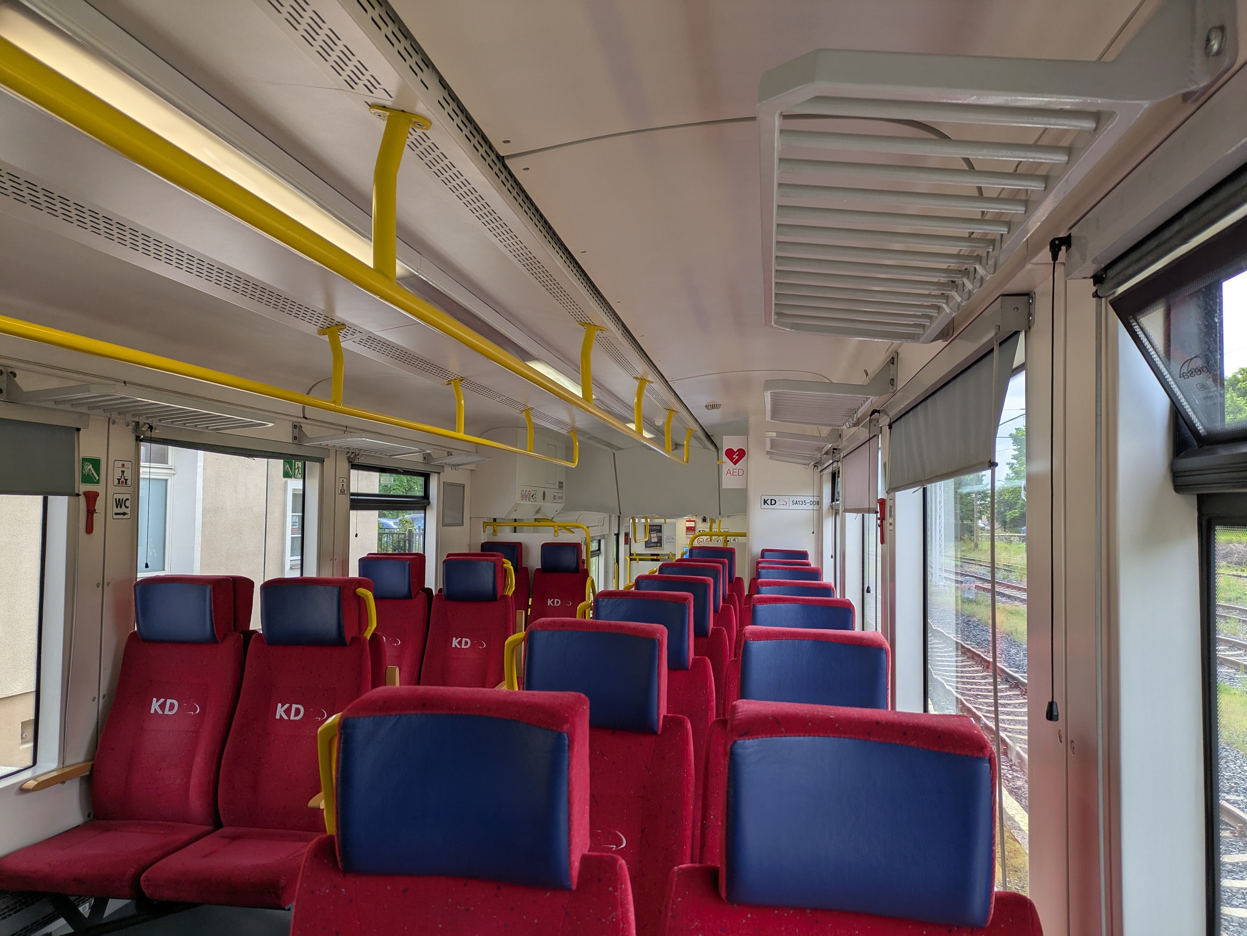
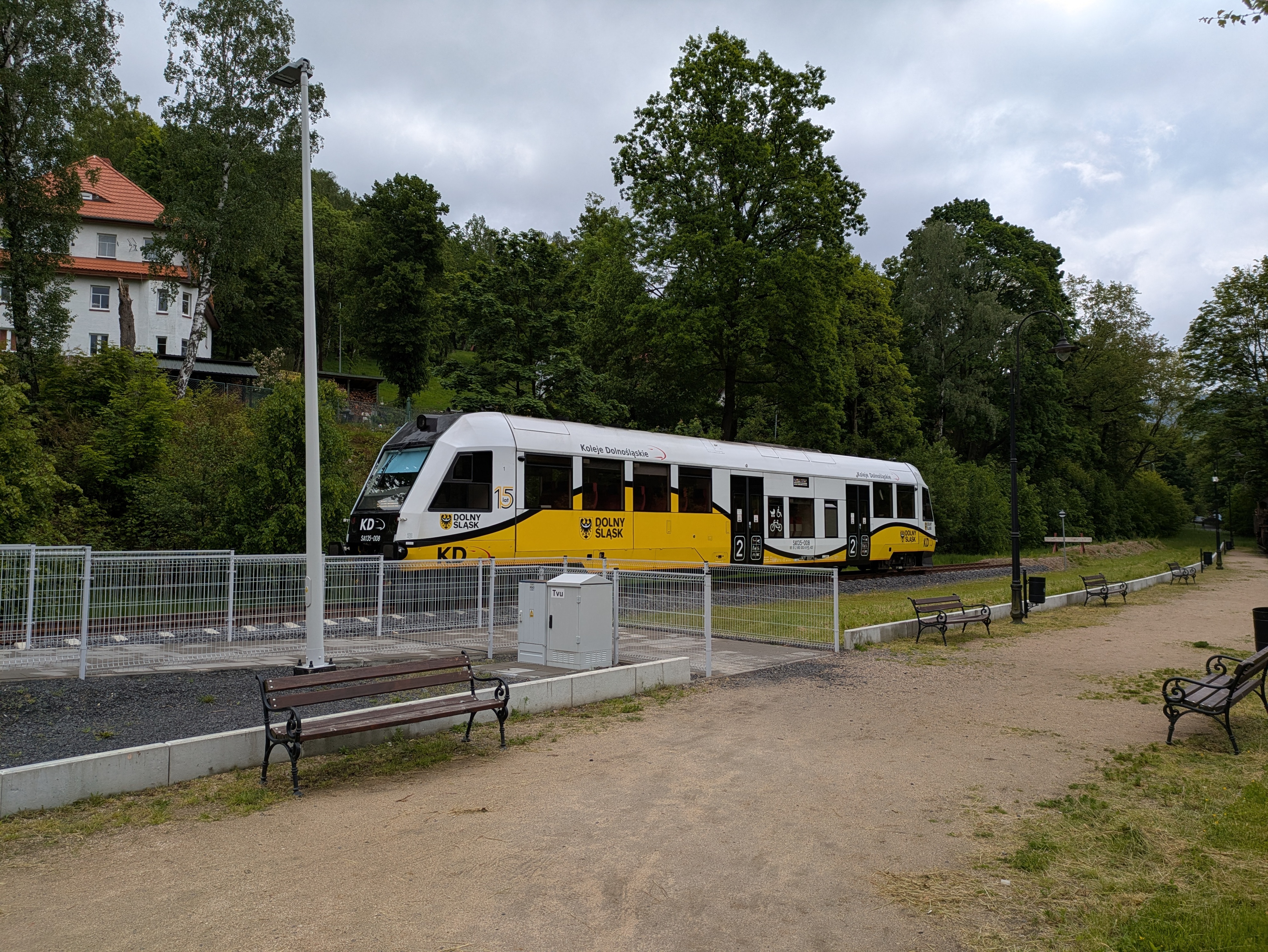
- KD D62 Karpacz (09:00) → Jelenia Góra (09:18)
- KD D6 Jelenia Góra (09:24) → Szklarska Poreba Górna (10:15)
Pramen Labe
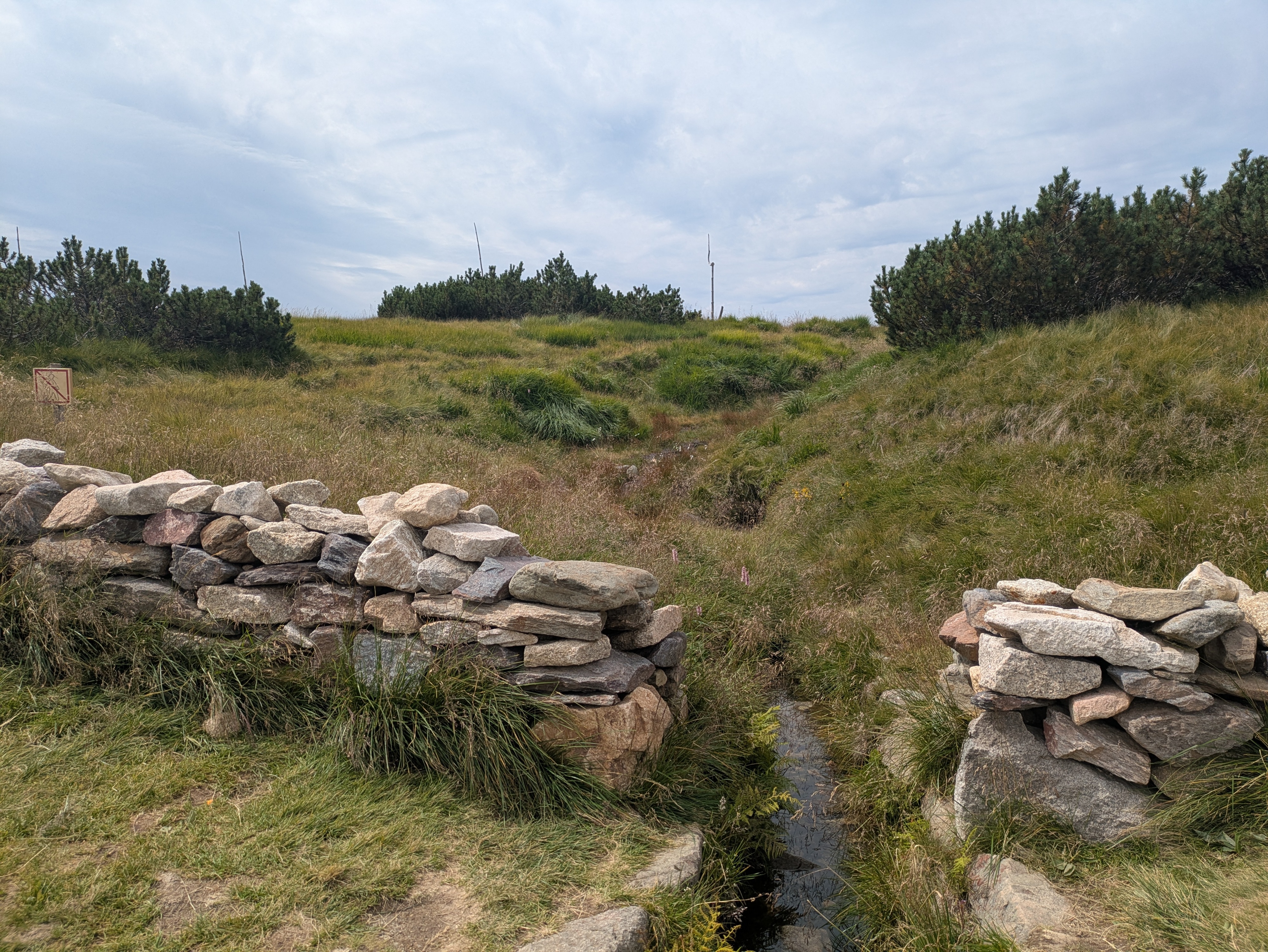
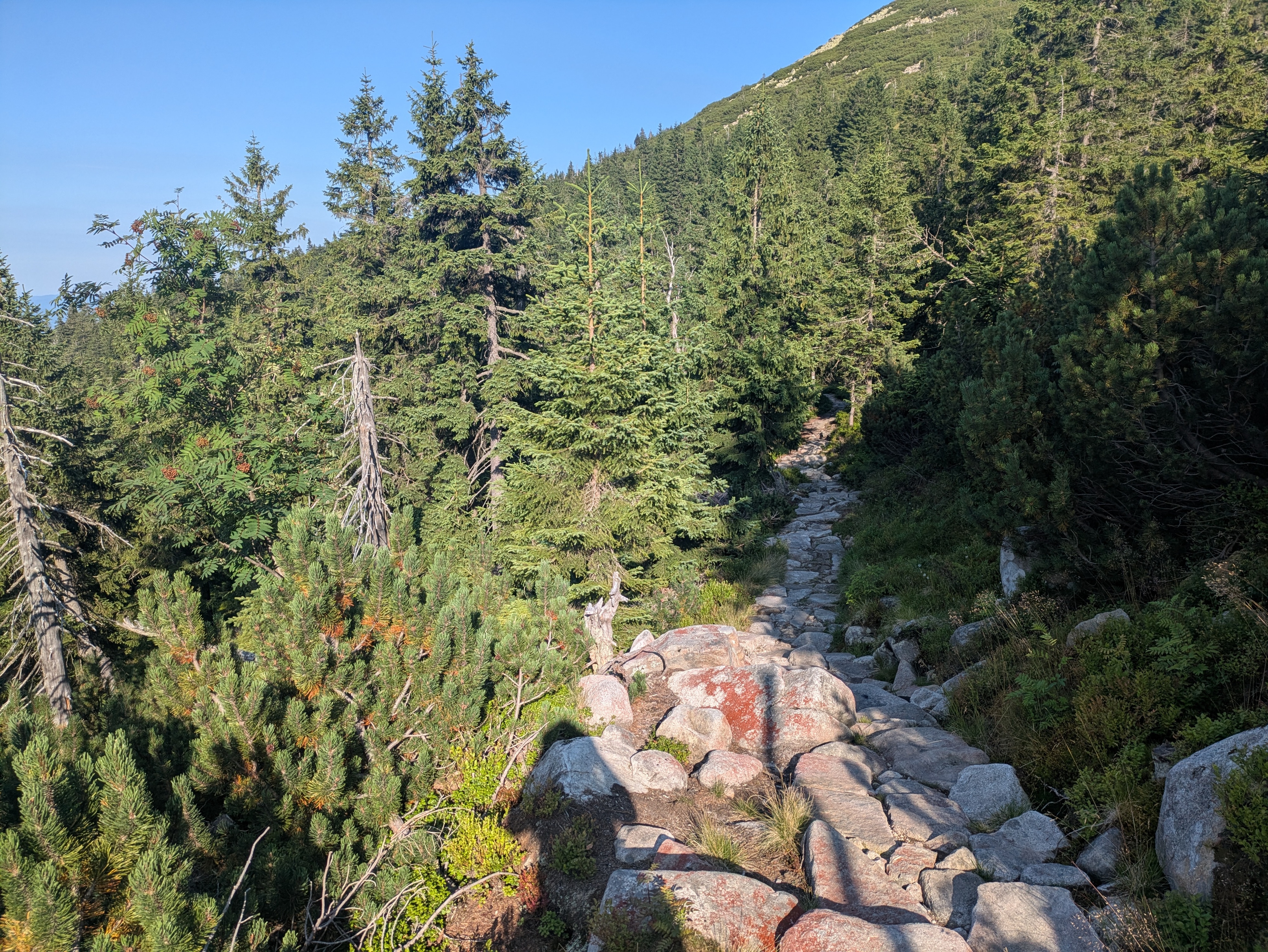
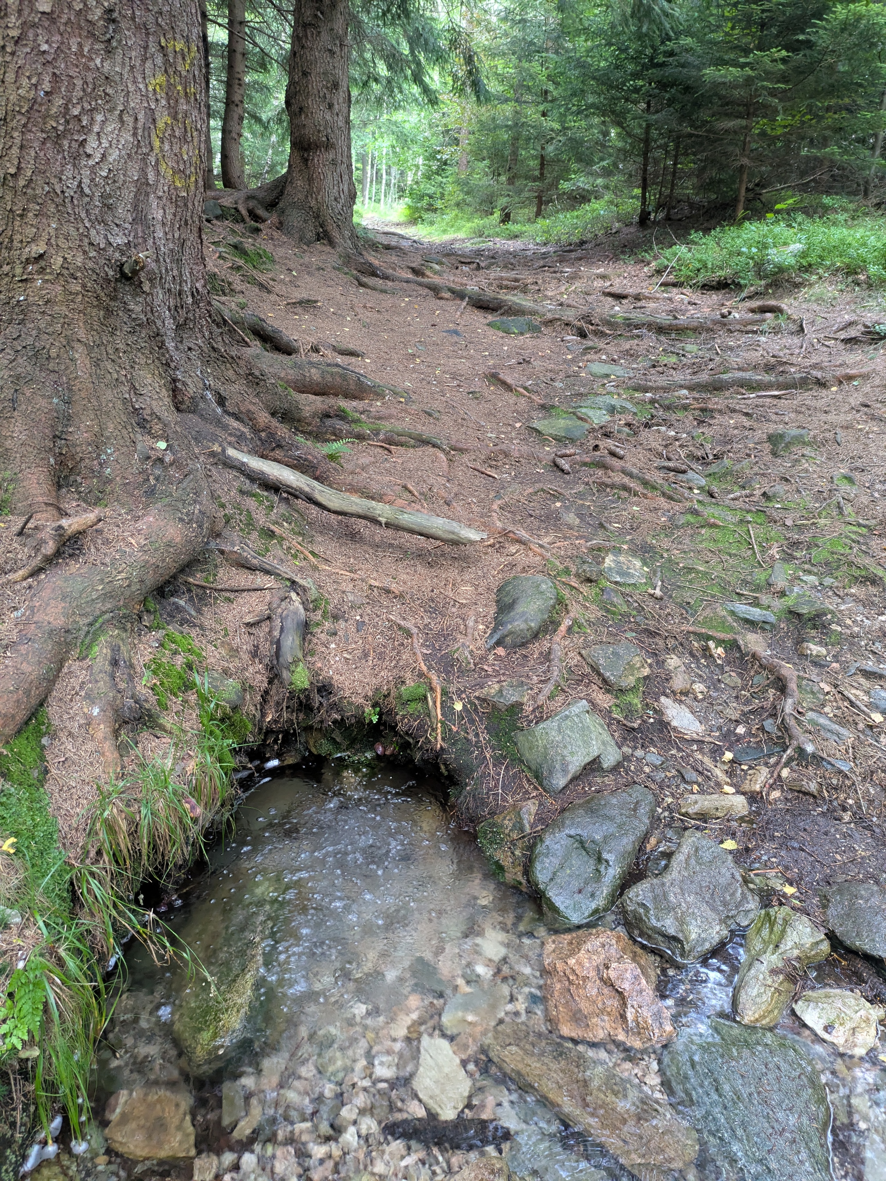
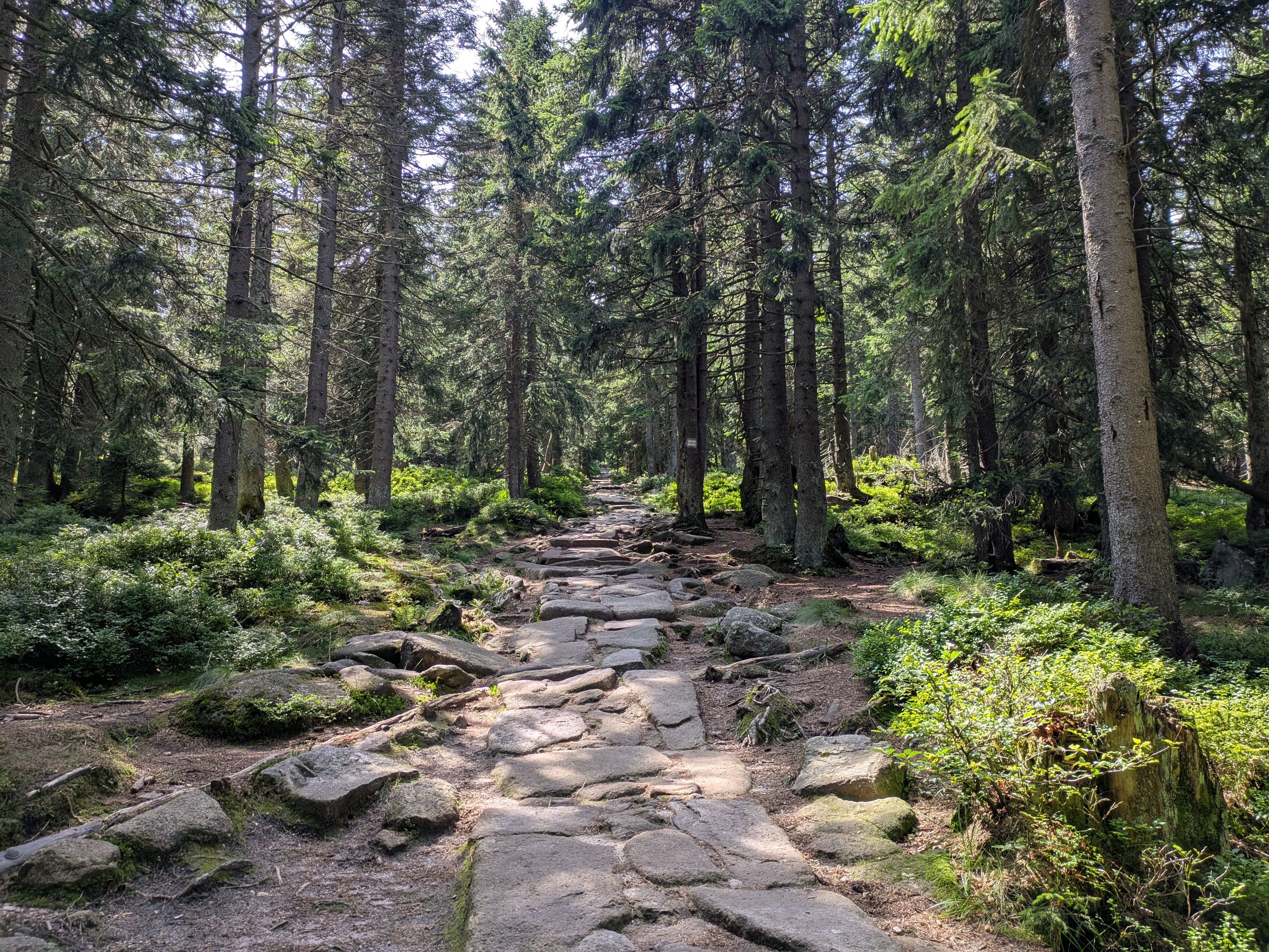
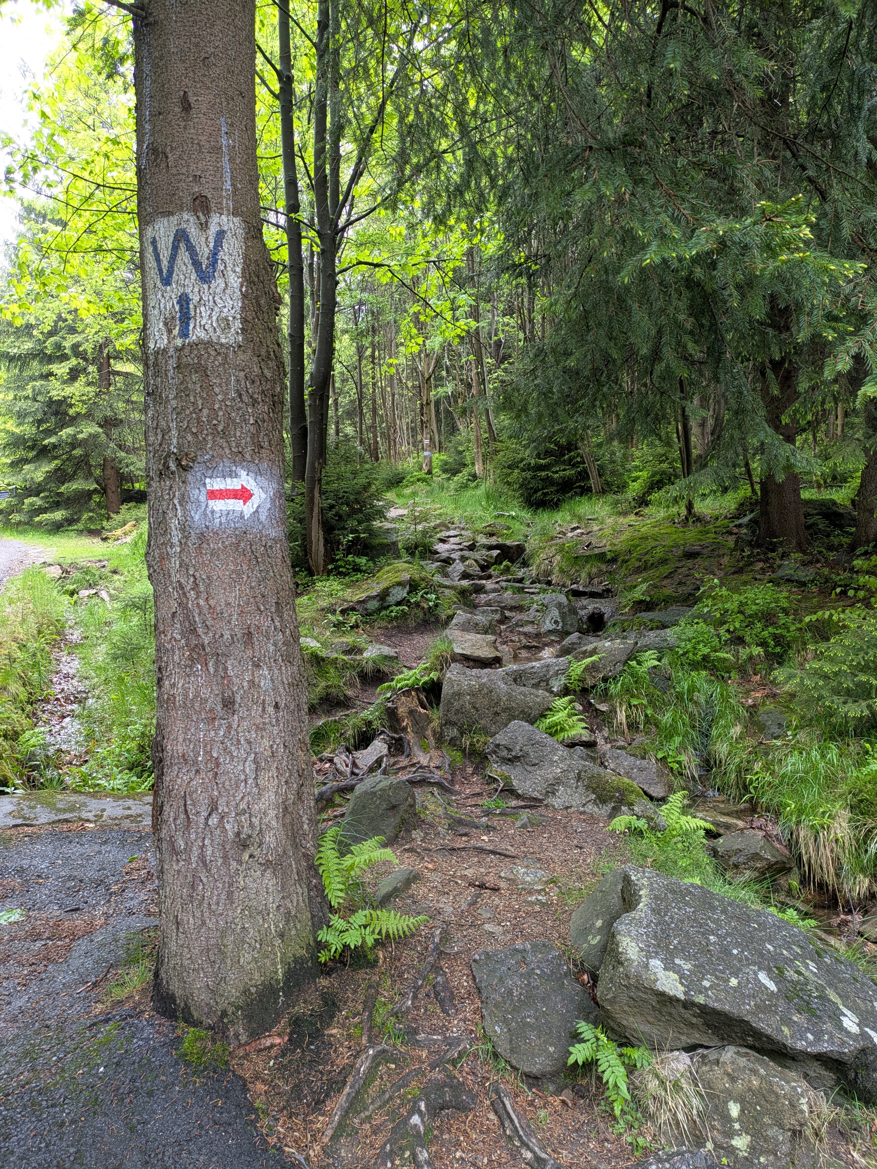
Szklarska Poreba is a comfortable little town, and seems like less of a tourist attraction than Karpacz. Only downside: it's located in a valley, with the train station where we got off sitting on the hills on one side and the Giant Mountains on the other. So, we first had to lose some precious elevation only to climb back up again on the other side. Apart from that, the way up went as usual: it started out relatively smooth and even, and then got steep and stony. There were some more stone formations and water streams, but nothing out of the ordinary.
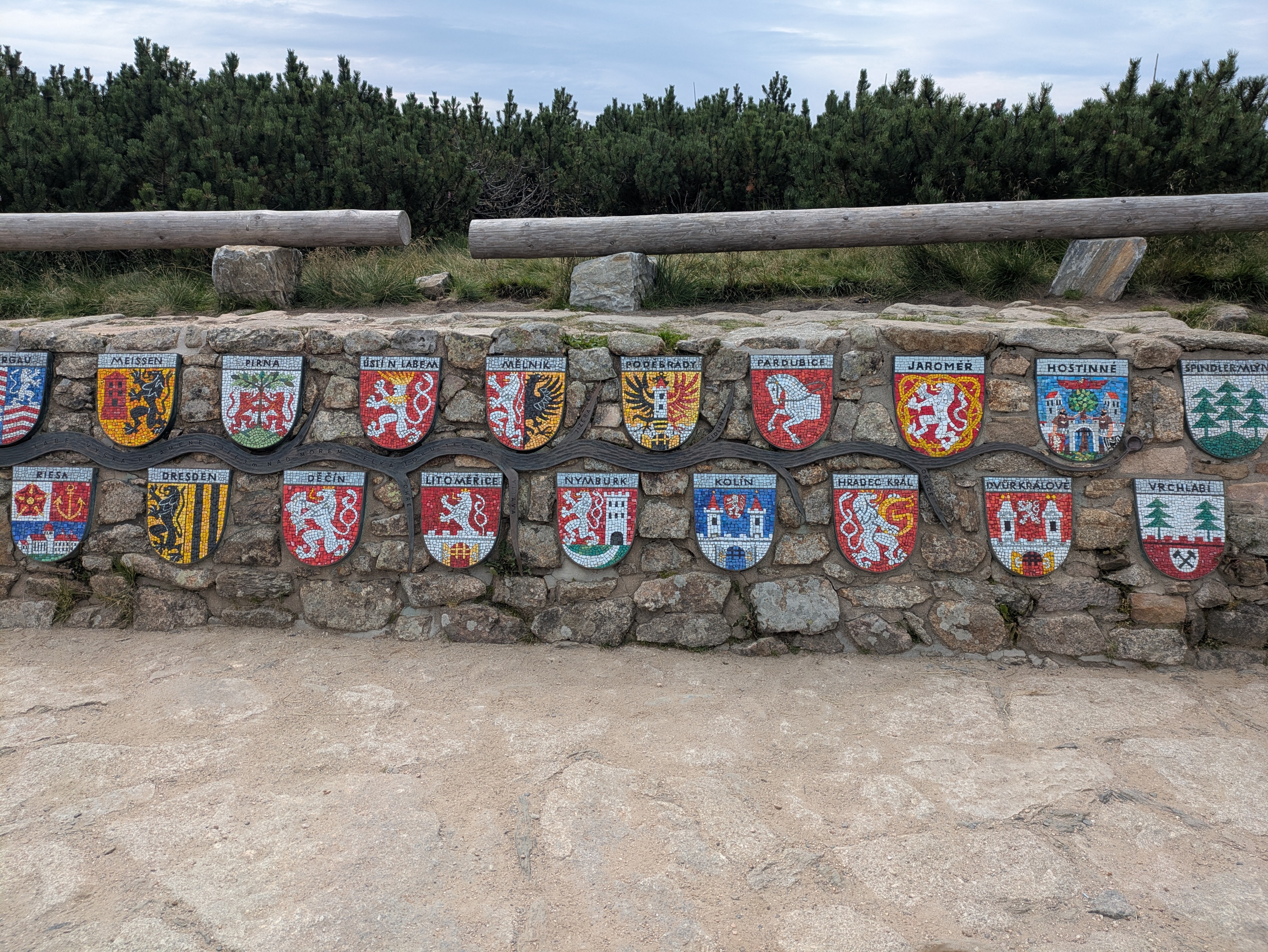
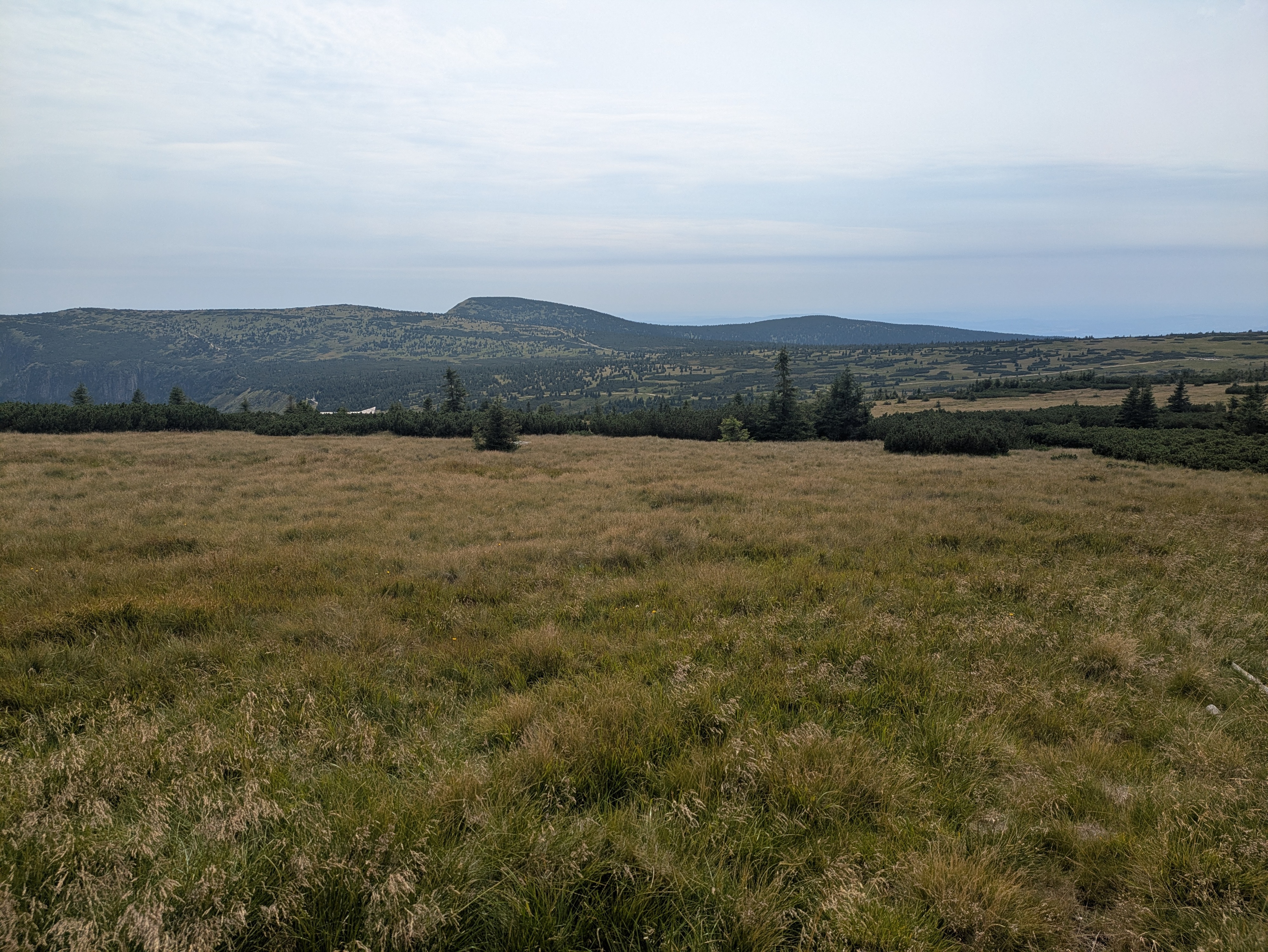
Pramen Labe was pretty crowded, so we didn't stay for too long (13:30 to 14:00 or so). The spring itself is your typical ordinary spring, augmented with a nice list of some of the towns and cities it passes before it finally flows into the North Sea. It's located on a relatively large plateau, so from the spring itself, you don't have that much of a view into the surrounding mountain- or countryside.
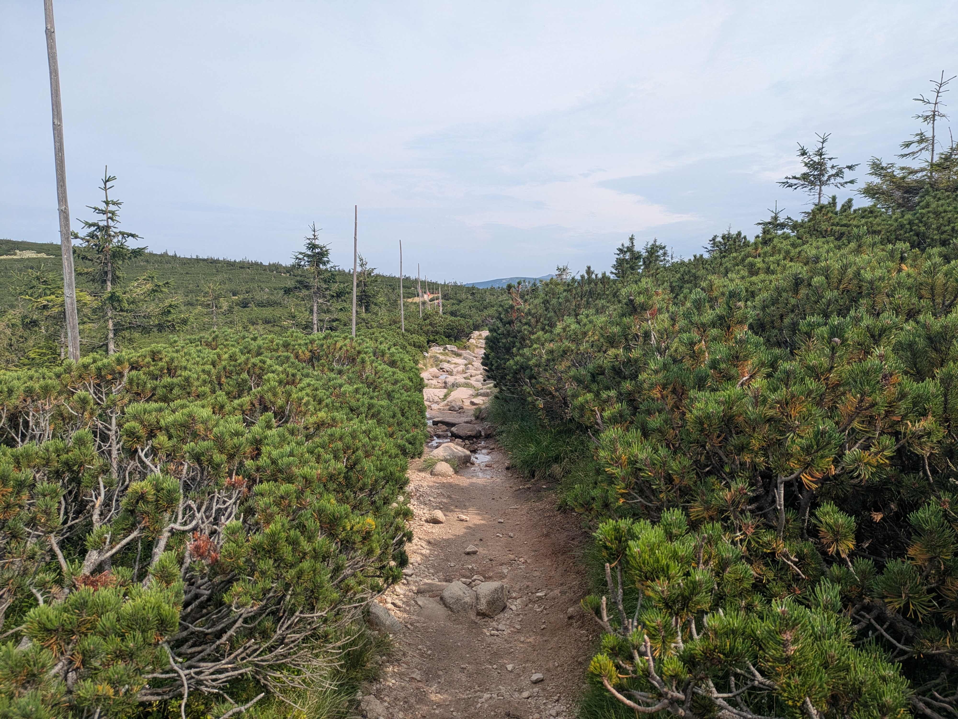
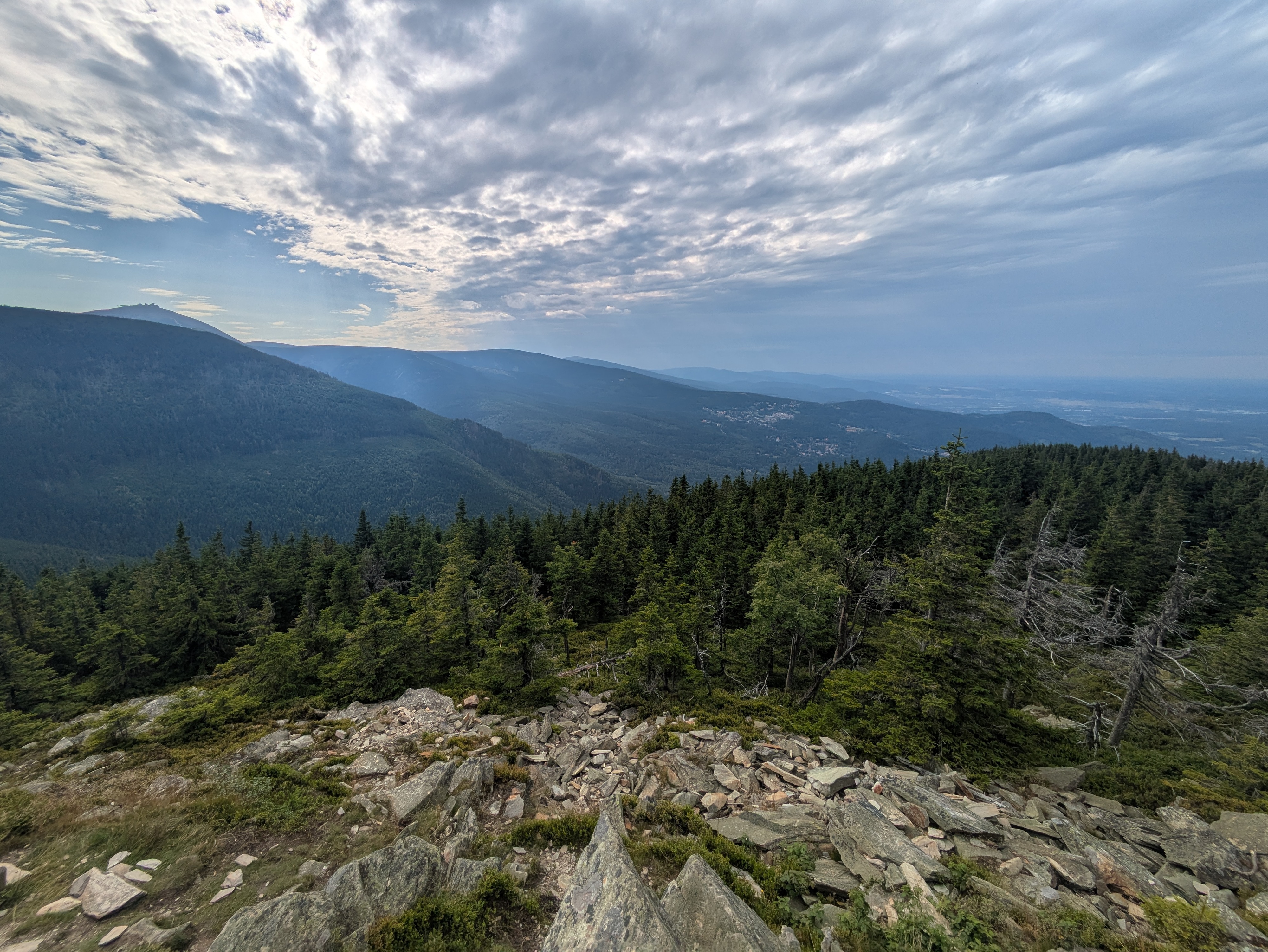
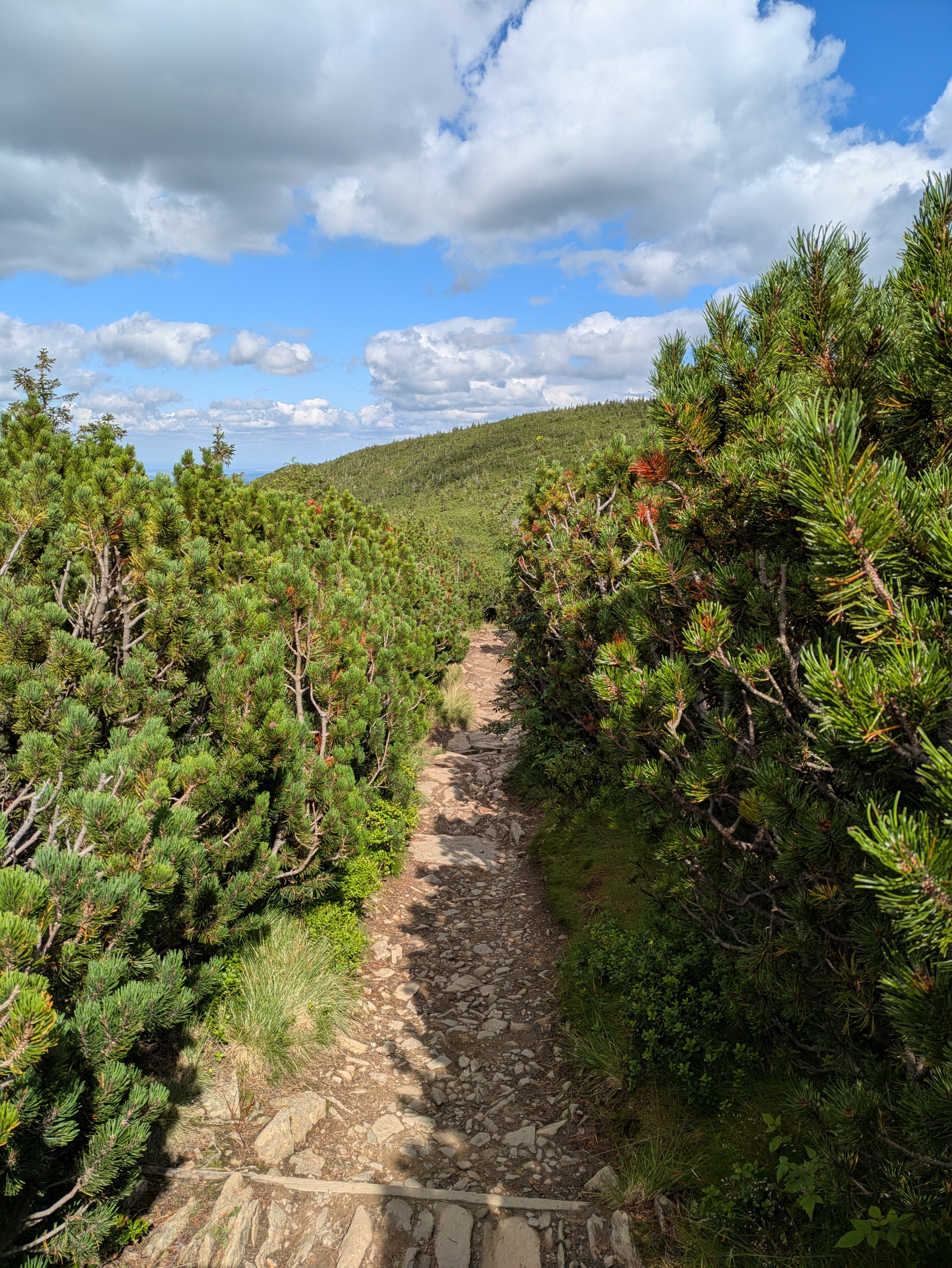
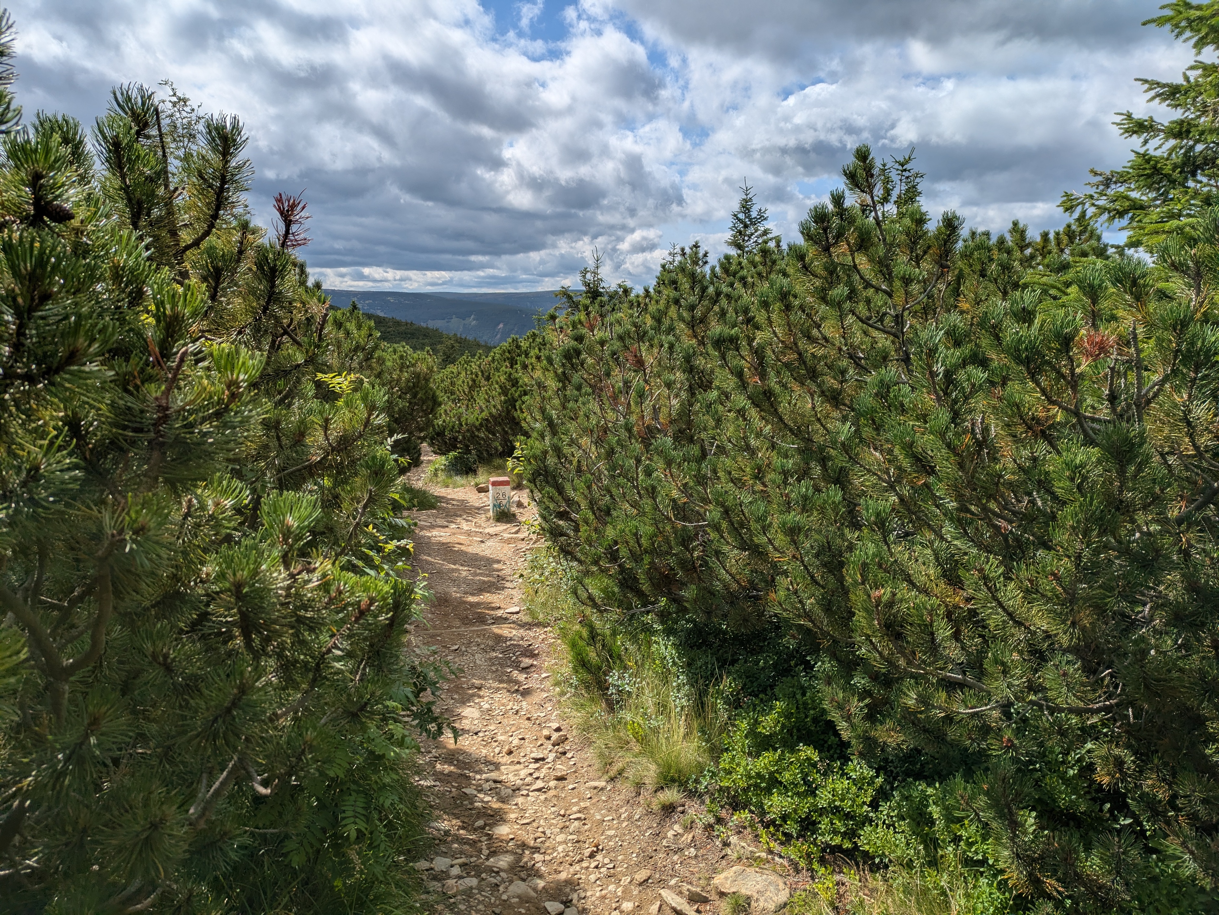
The Ridge
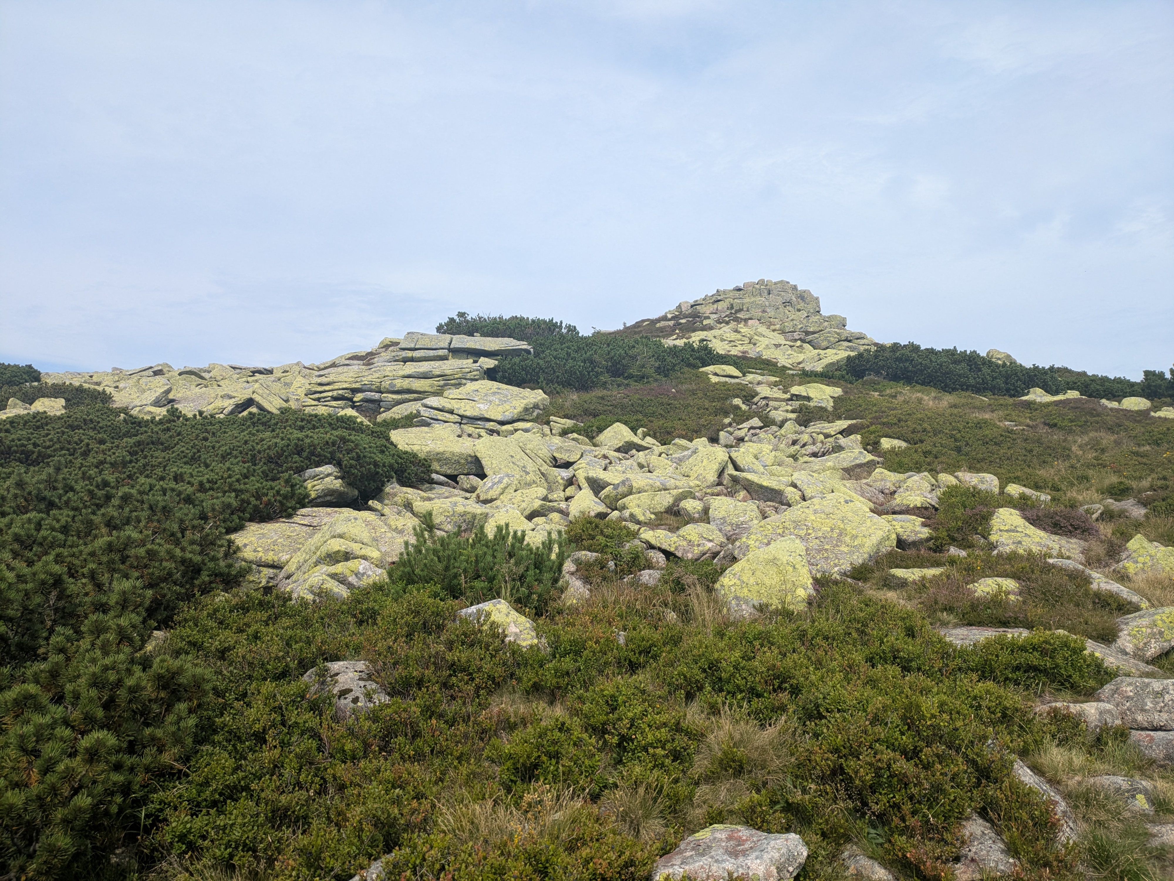
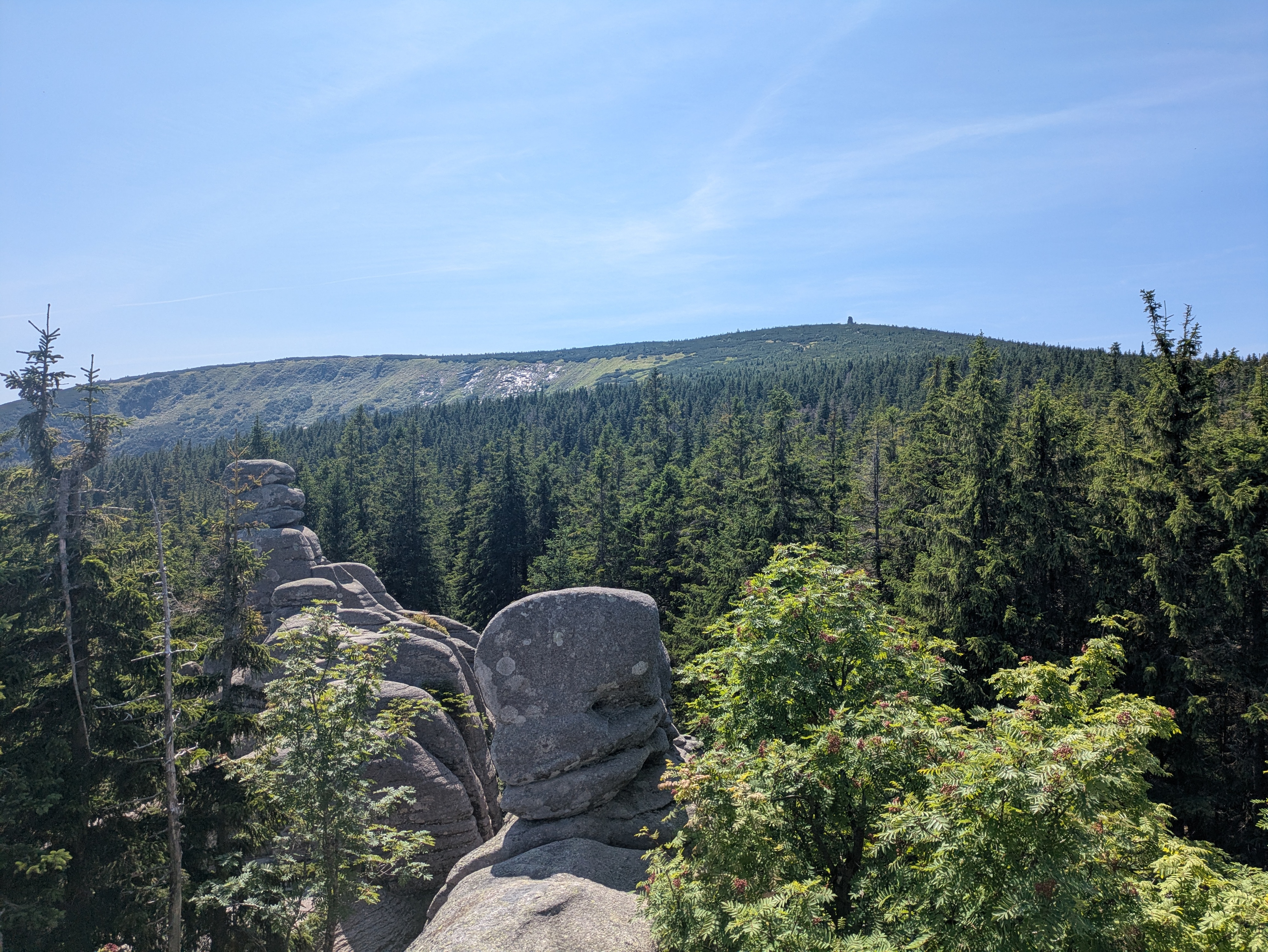
The first peak we passed was Violik / Łabski Szczyt (Veilchenstein / violet peak). Apparently, its granite rock is slowly ground down by freezing water, leading to its slightly unnatural look as if someone had used a large shovel to pile up a heap of stones. It was also home to some prime specimen of some kind of moss, possibly Trentepohlia iolithus (Veilchenmoos) or Psilolechia lucida (Schwefelflechte).
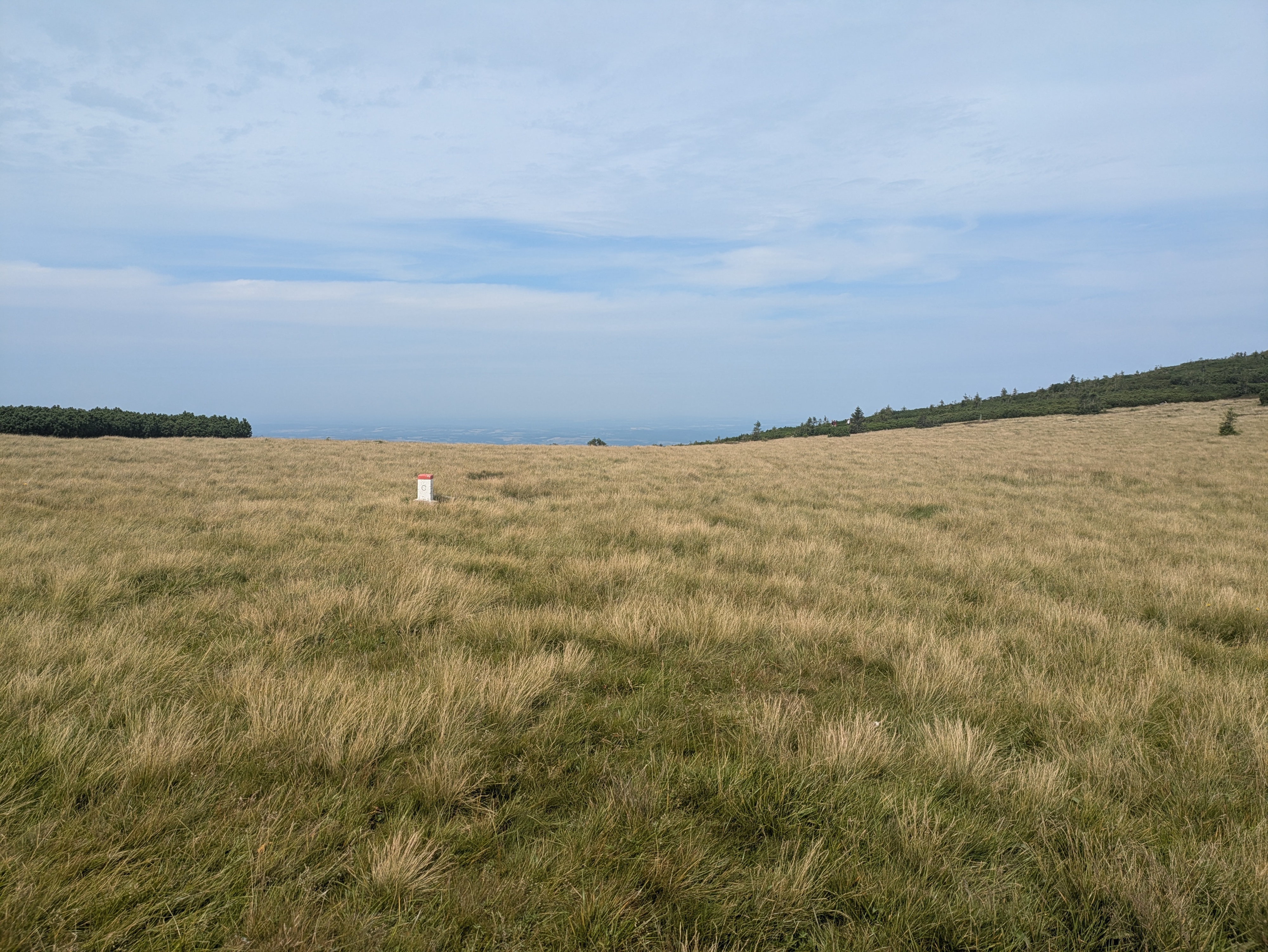
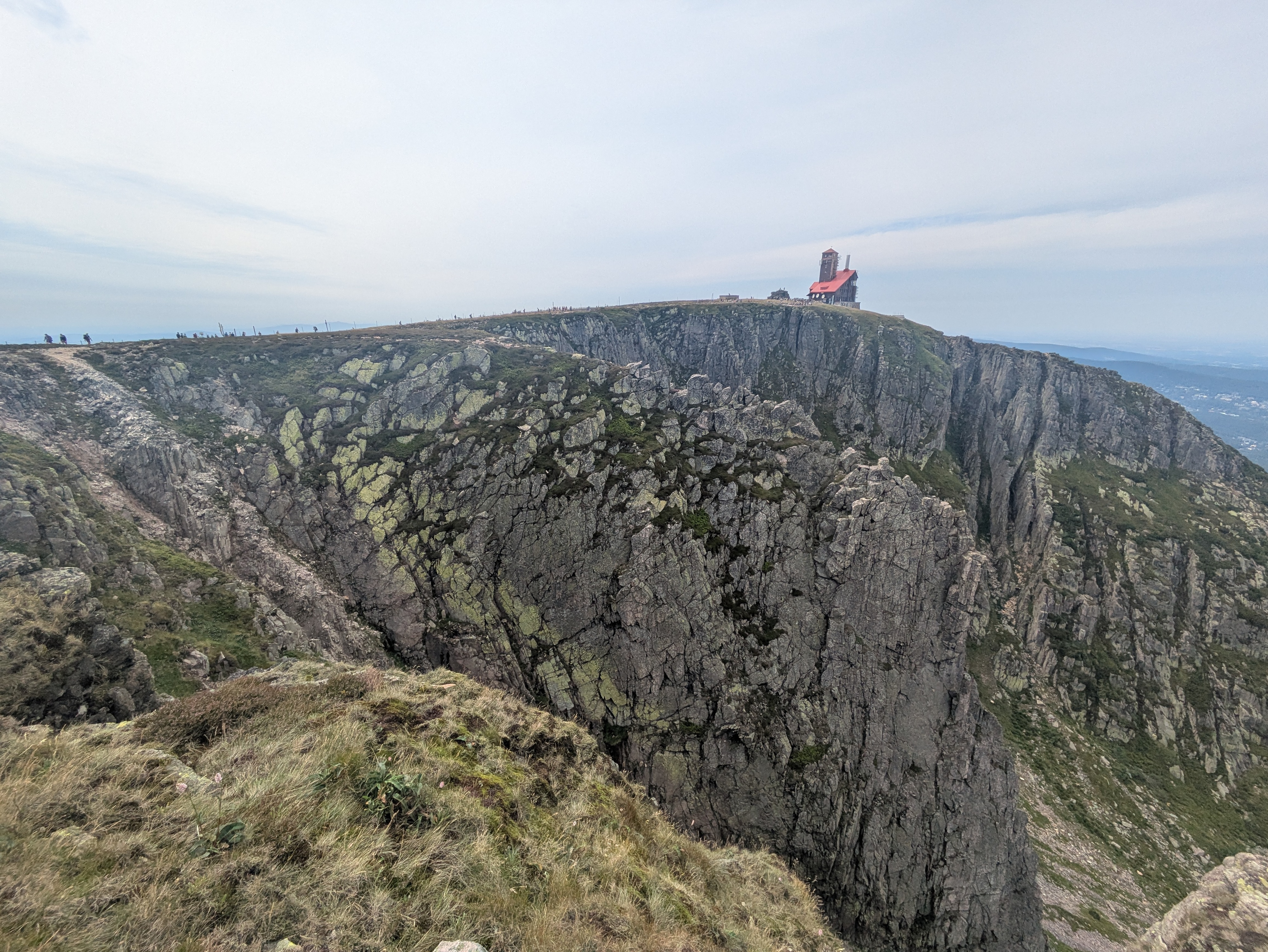
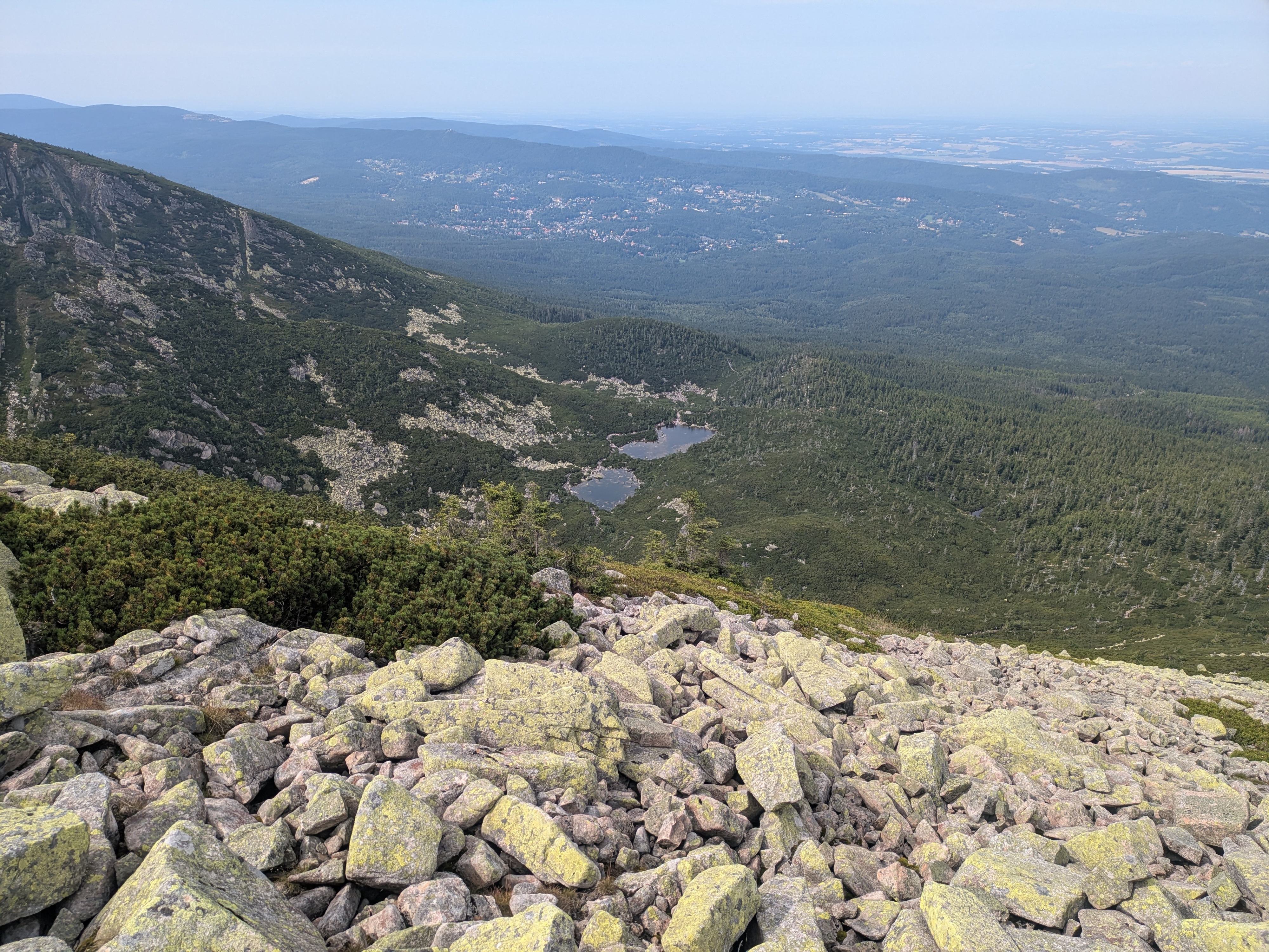
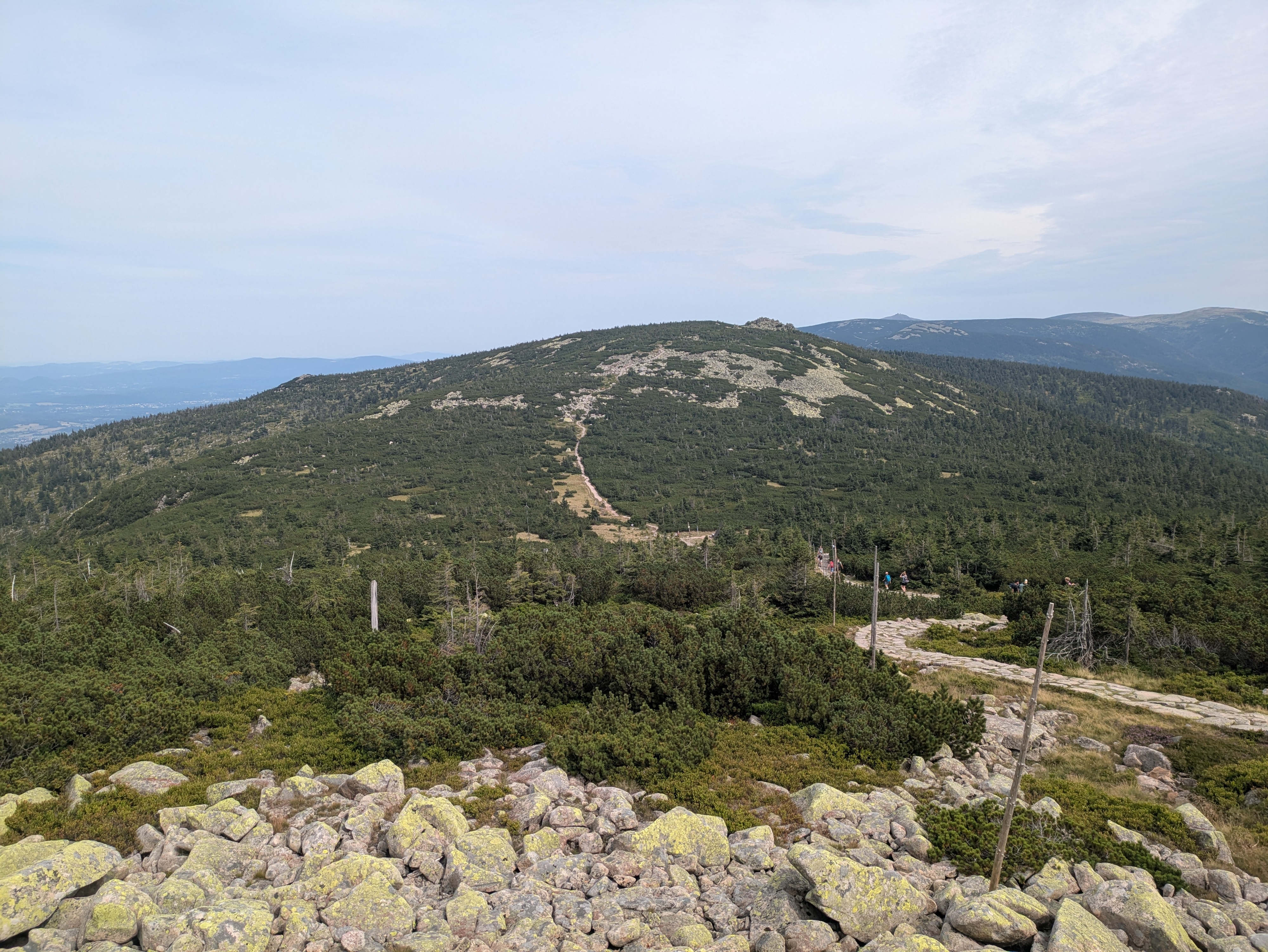
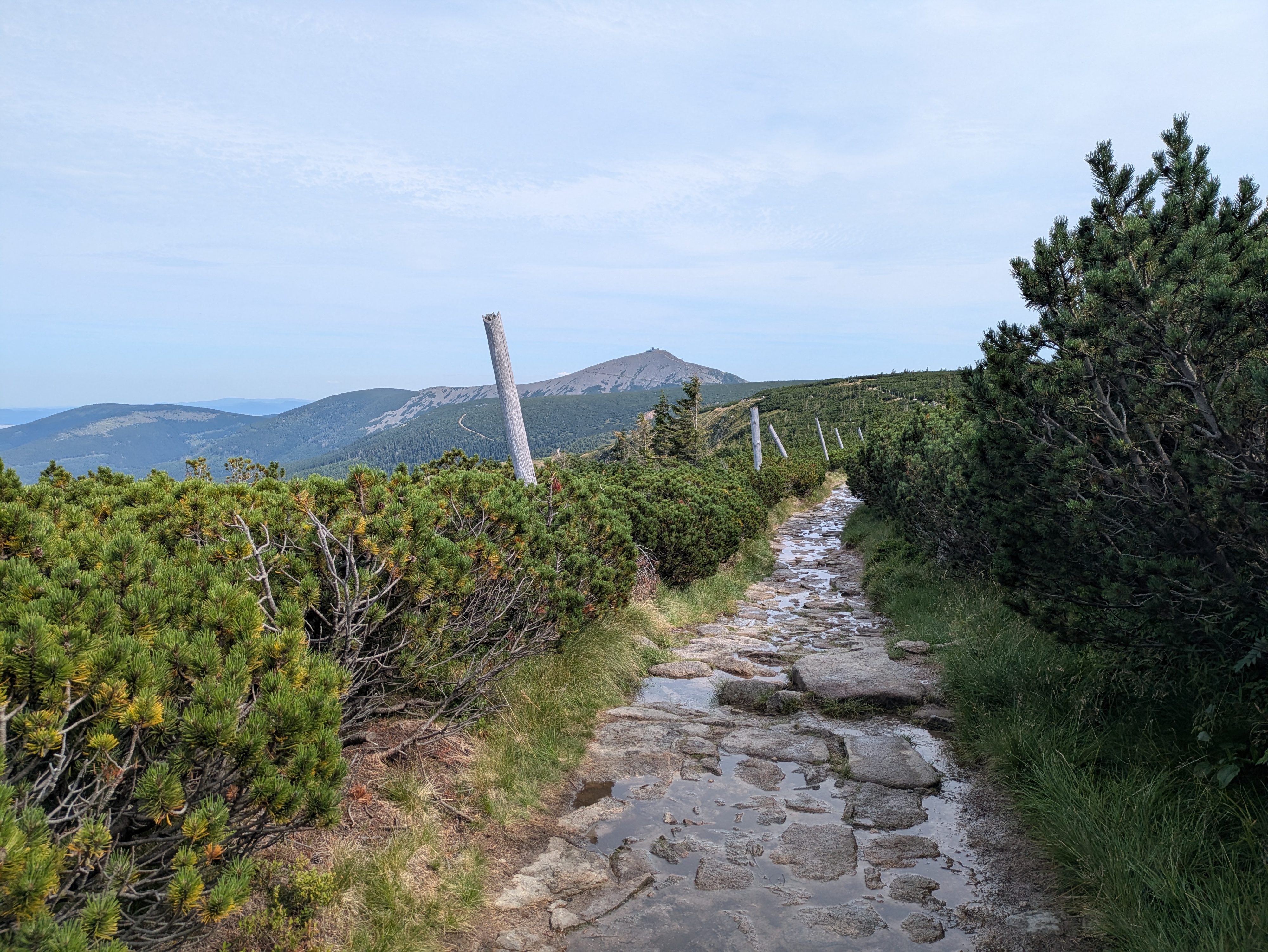
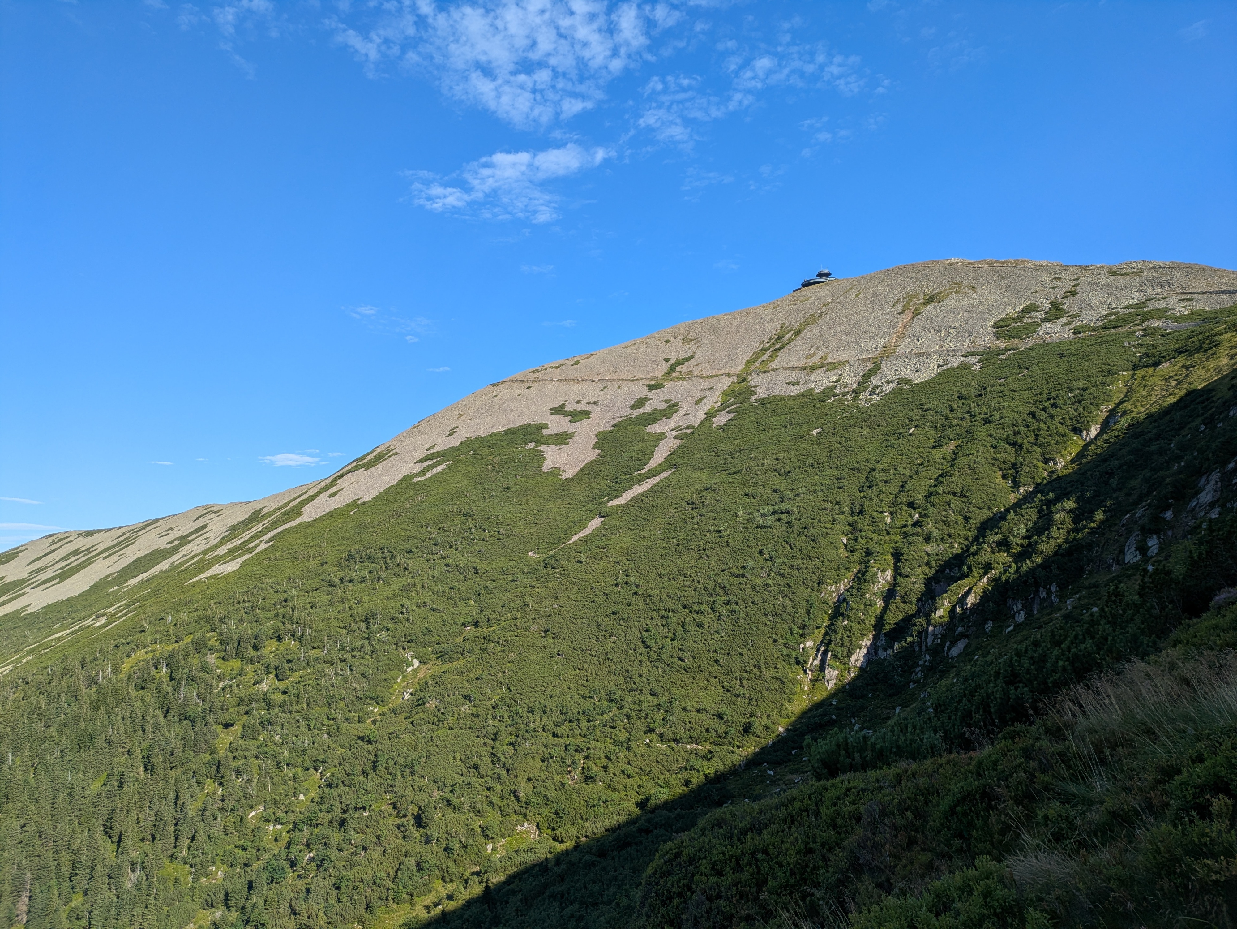
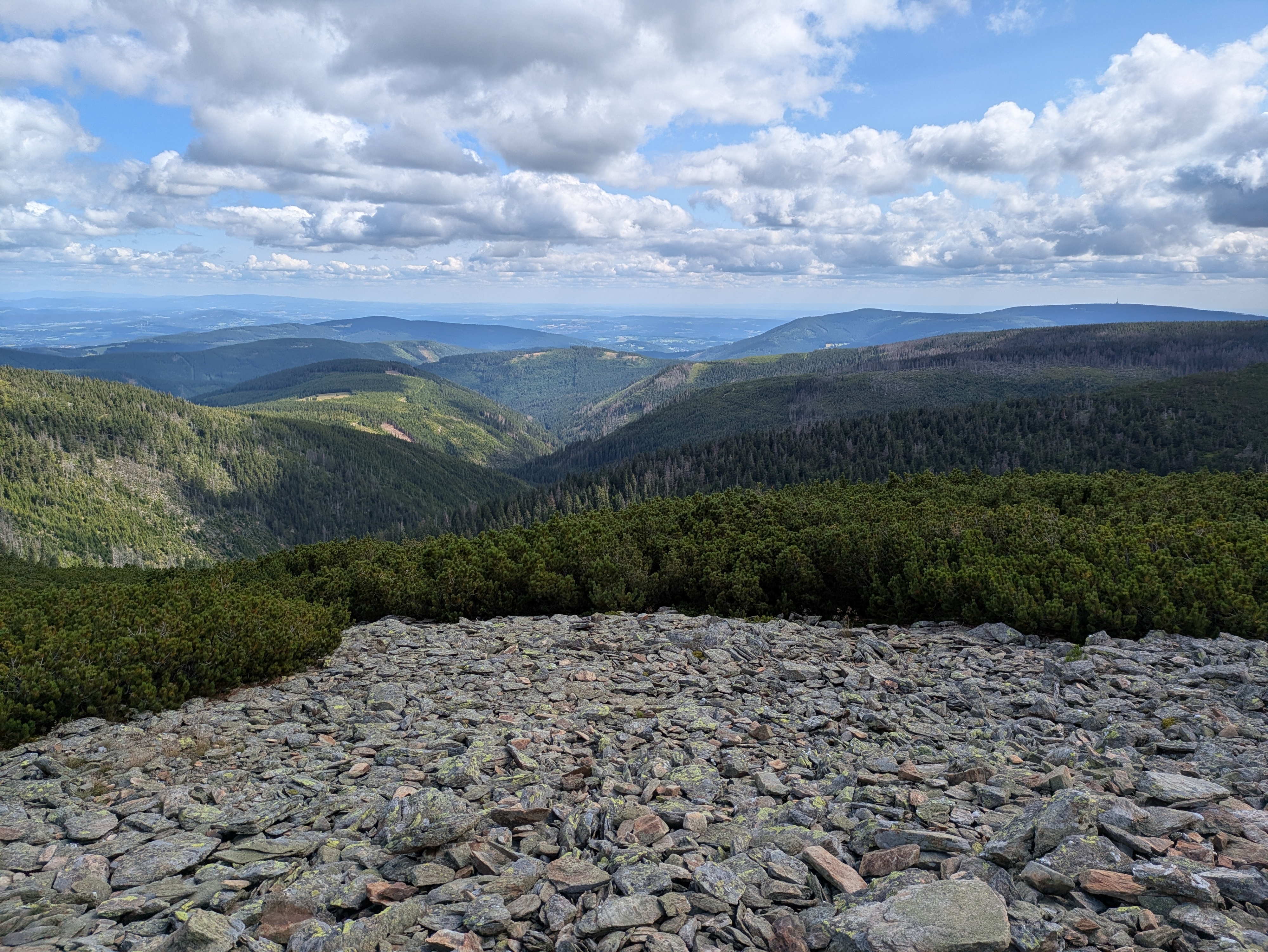
Up next were Vysoká pláň (high plain), a small peak located on a wide plateau that sits at about 1,400 metres above sea level, and the neighbouring Śnieżne Kotły (Schneegruben / snow pits). Vysoká pláň features the former Schronisko „Nad Śnieżnymi Kotłami” (Schneegrubenbaude / shelter “above the snow pits”), which used to offer rest to hikers and mountain climbers. These days, it is instead used as a radio tower: Radiowo-telewizyjny Ośrodek Nadawczy Śnieżne Kotły. Śnieżne Kotły tend to be a repository for not-yet-molten snow late into spring, but were absolutely devoid of it when we passed them in early August. In any case, the view from the upper side of the cliff was quite spectacular. We spent a few minutes admiring the views, and continued at about 15:00.
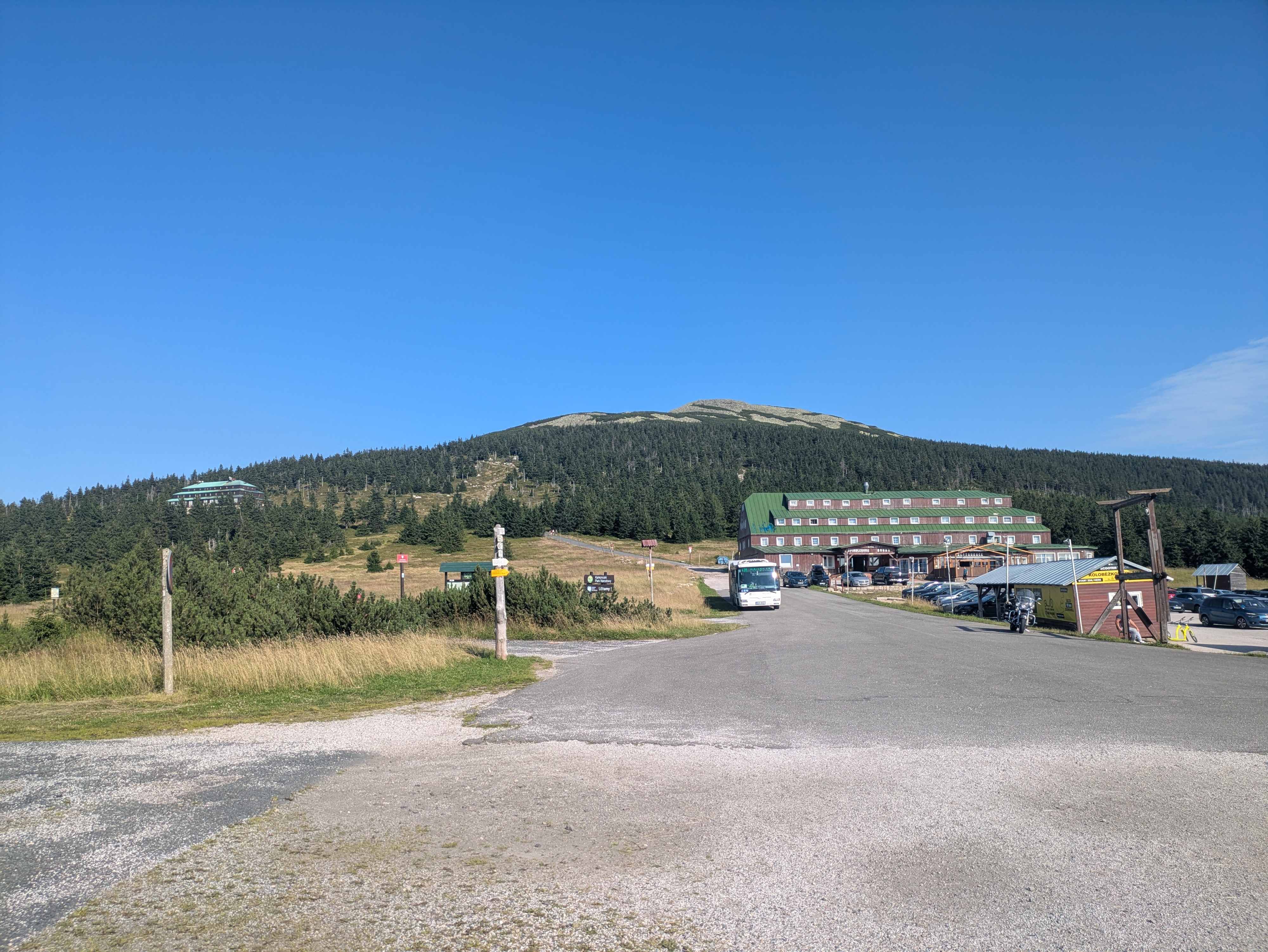
We continued around Vysoké kolo (Hohes Rad / high wheel), whose peak consists entirely of broken granite, towards Špindlerova bouda (Spindlerbaude / Špindler's hut), a former shelter that now serves as a hotel.
The peak of vysoké kolo really is quite impressive – I only have pictures of the hiking path around it; see the Wikipedia links for more. Some of the rocks on the path are loose and there are no handrails or anything – do be careful where you step.
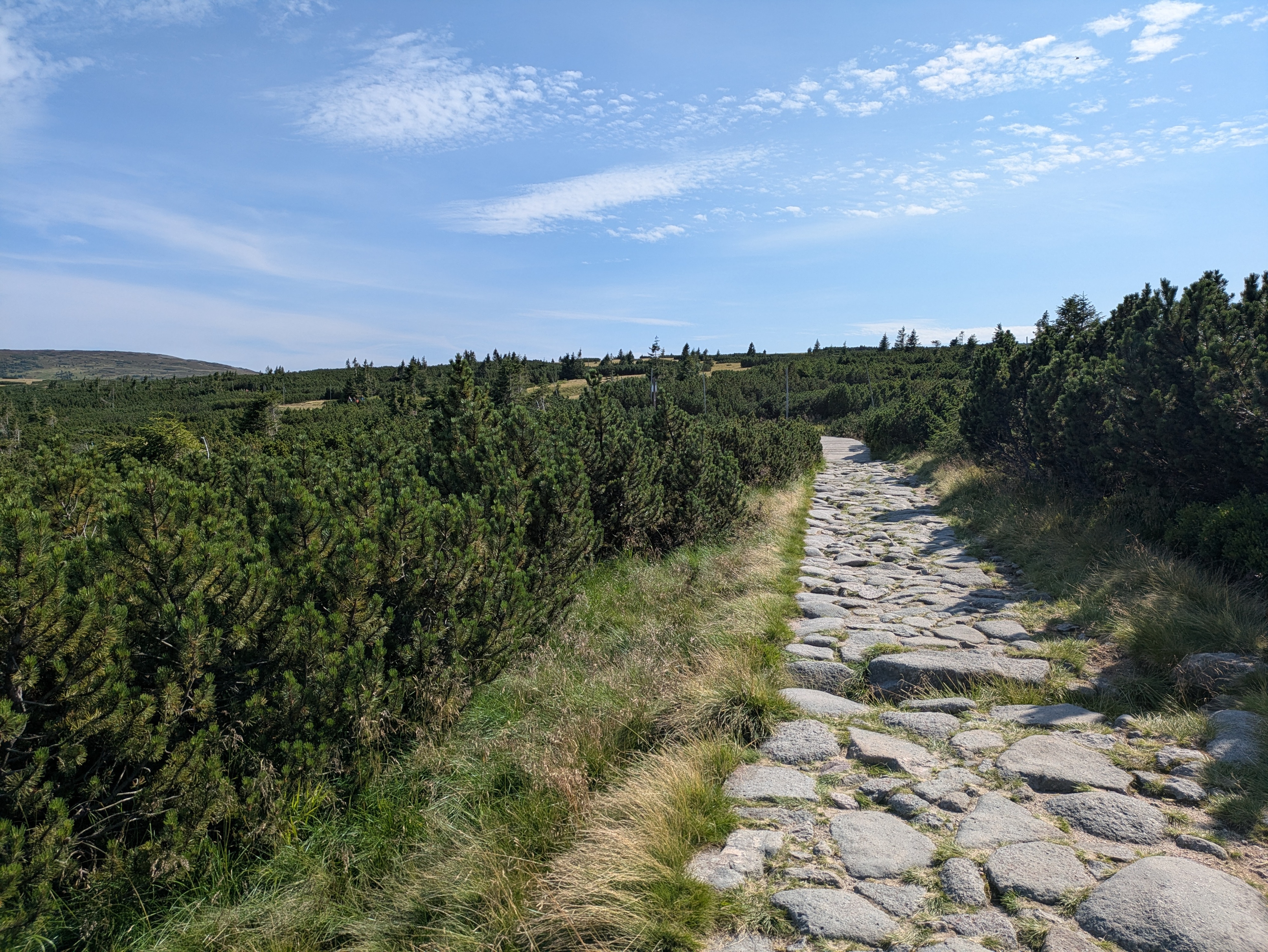
The remainder of the way towards Špindlerova bouda provided more granite heaps, mountain pines, and other kinds of rock formations. Also, Špindlerova bouda itself actually features a bus stop, located at convenient 1,198 metres above sea level.
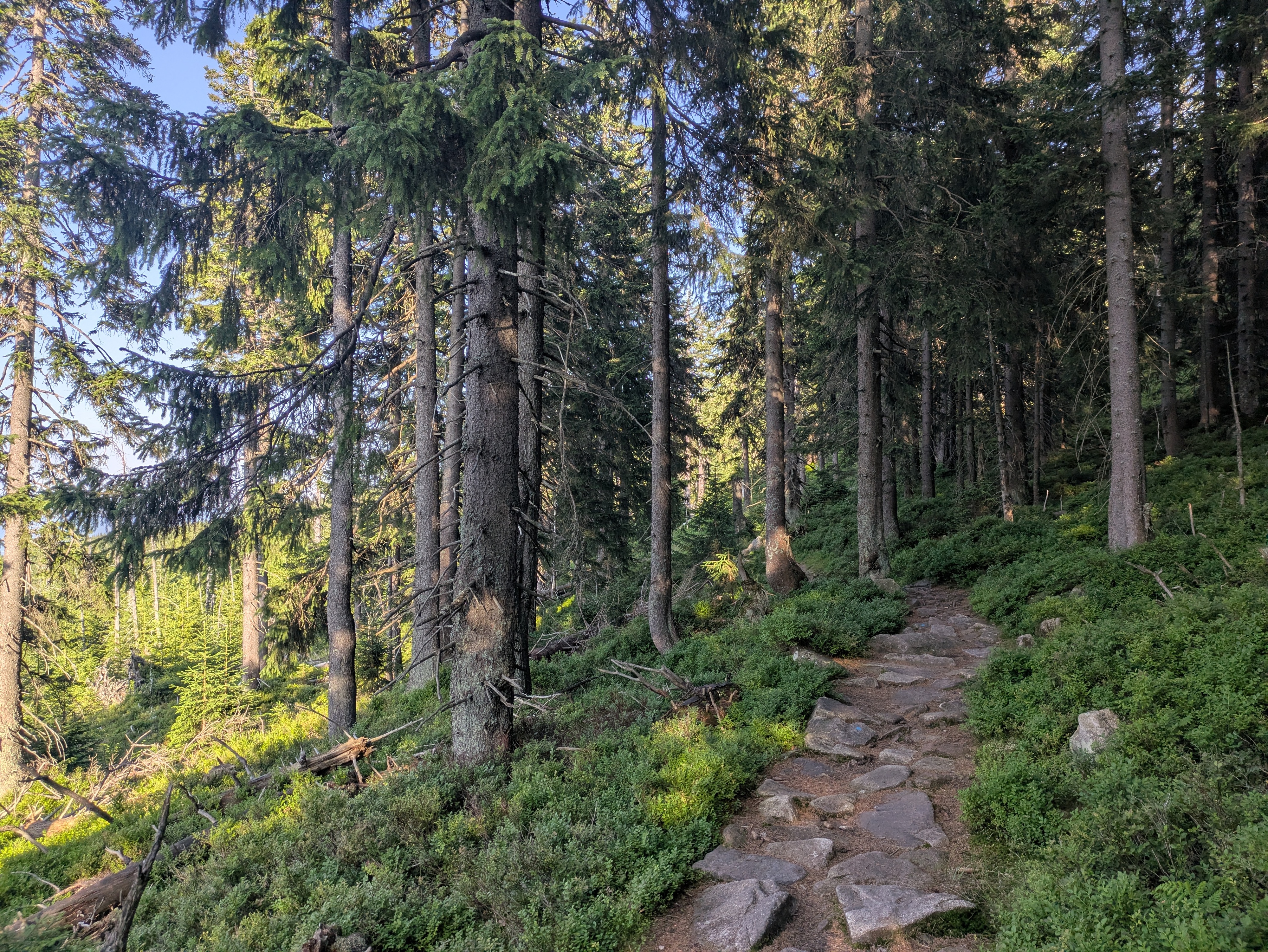
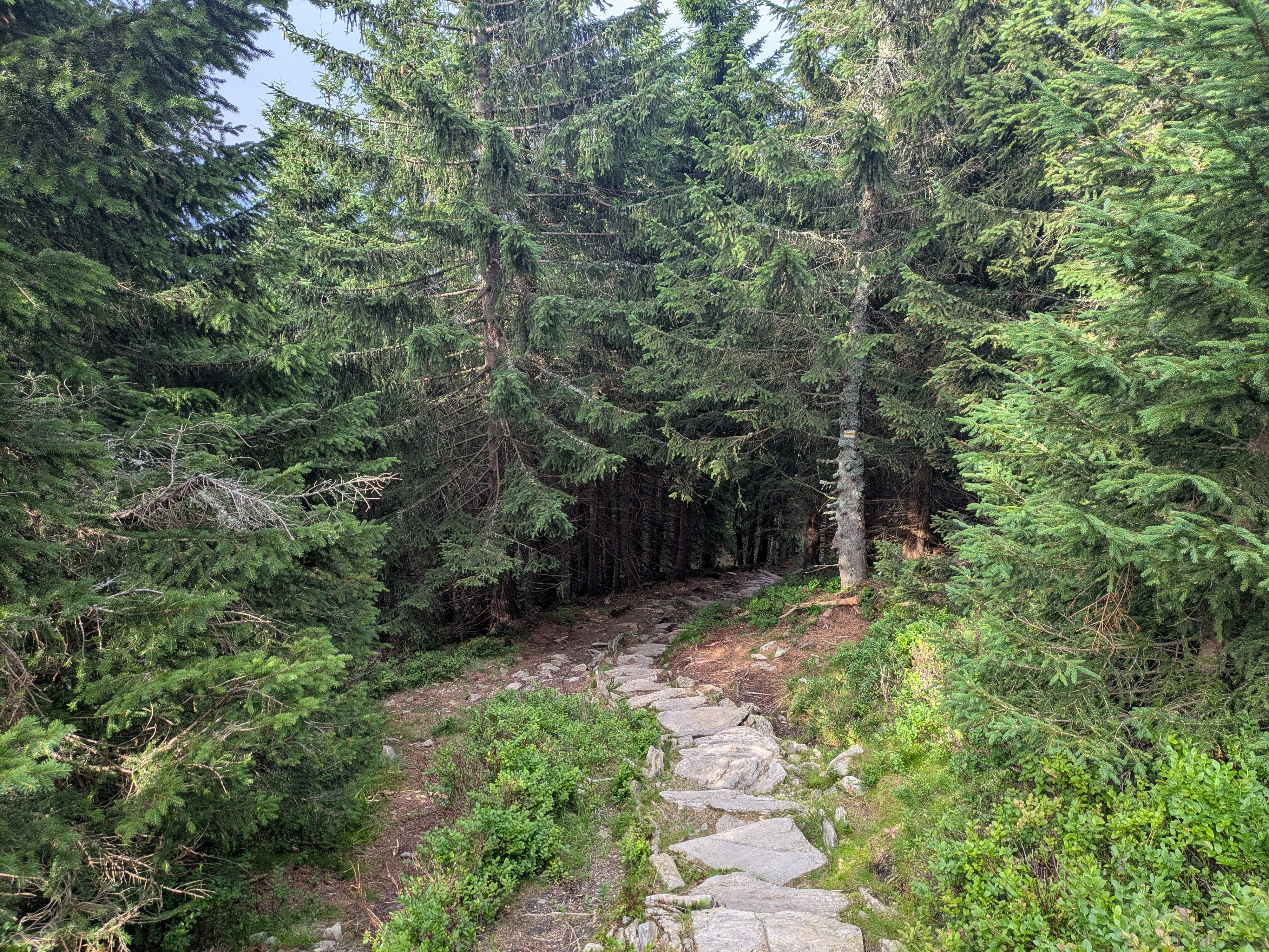
Descent
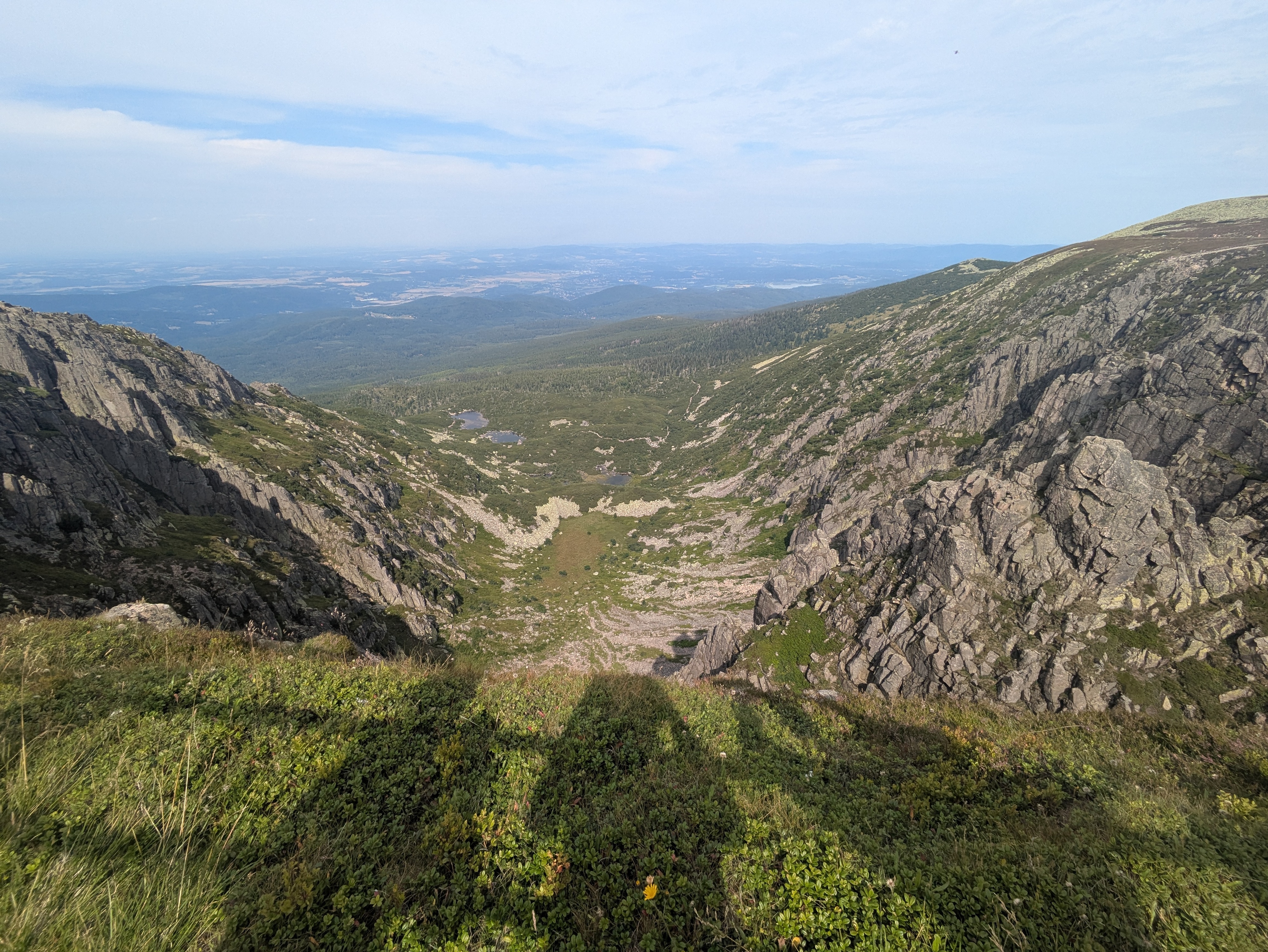
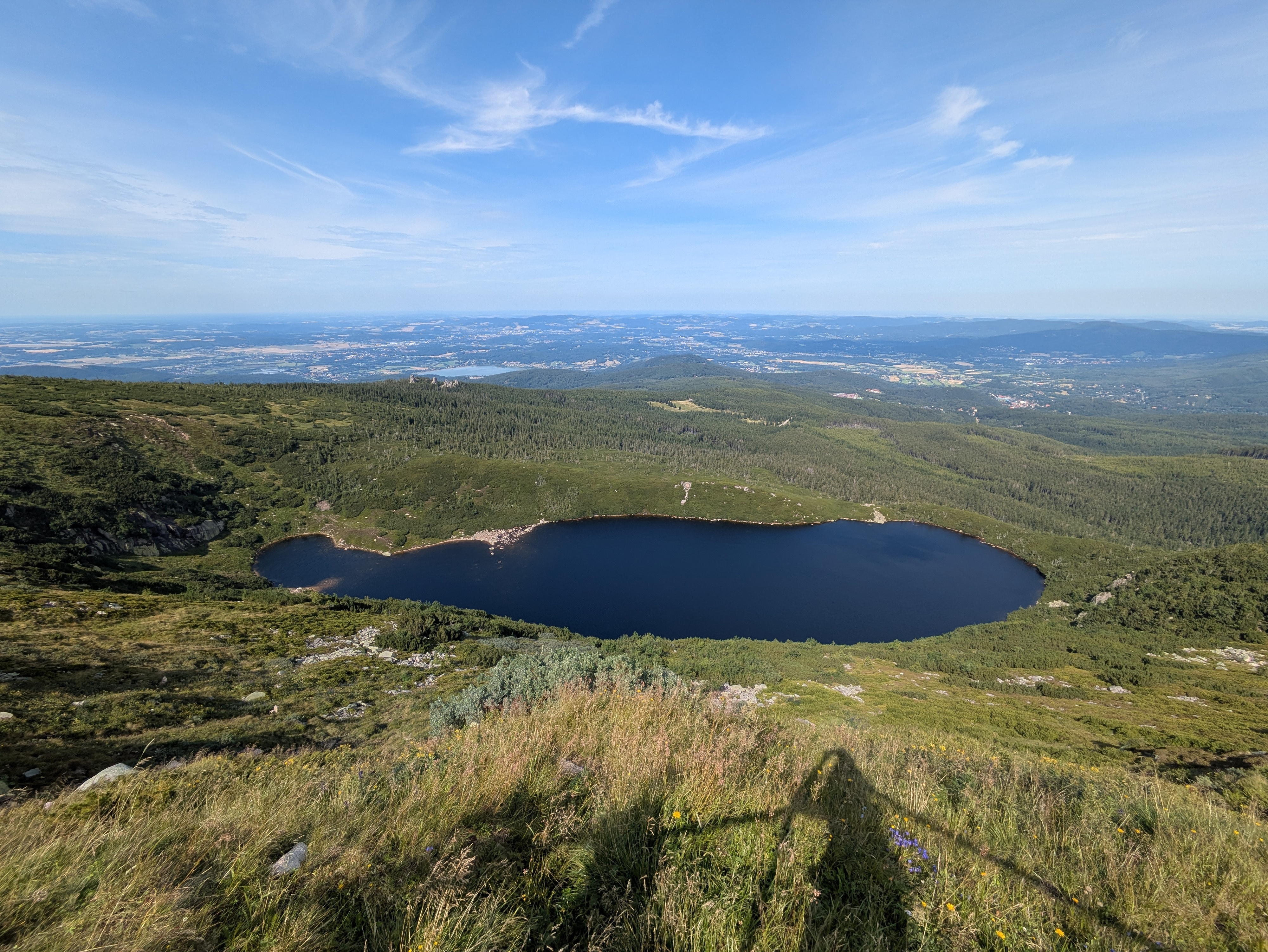
From here on, continuing the path along the peaks would have taken us to Słonecznik, which we had already visited two days ago. Instead, we descended to the north. We had actually planned to make our descent before Špindlerova bouda, however, it turned out that that path was closed to hikers.
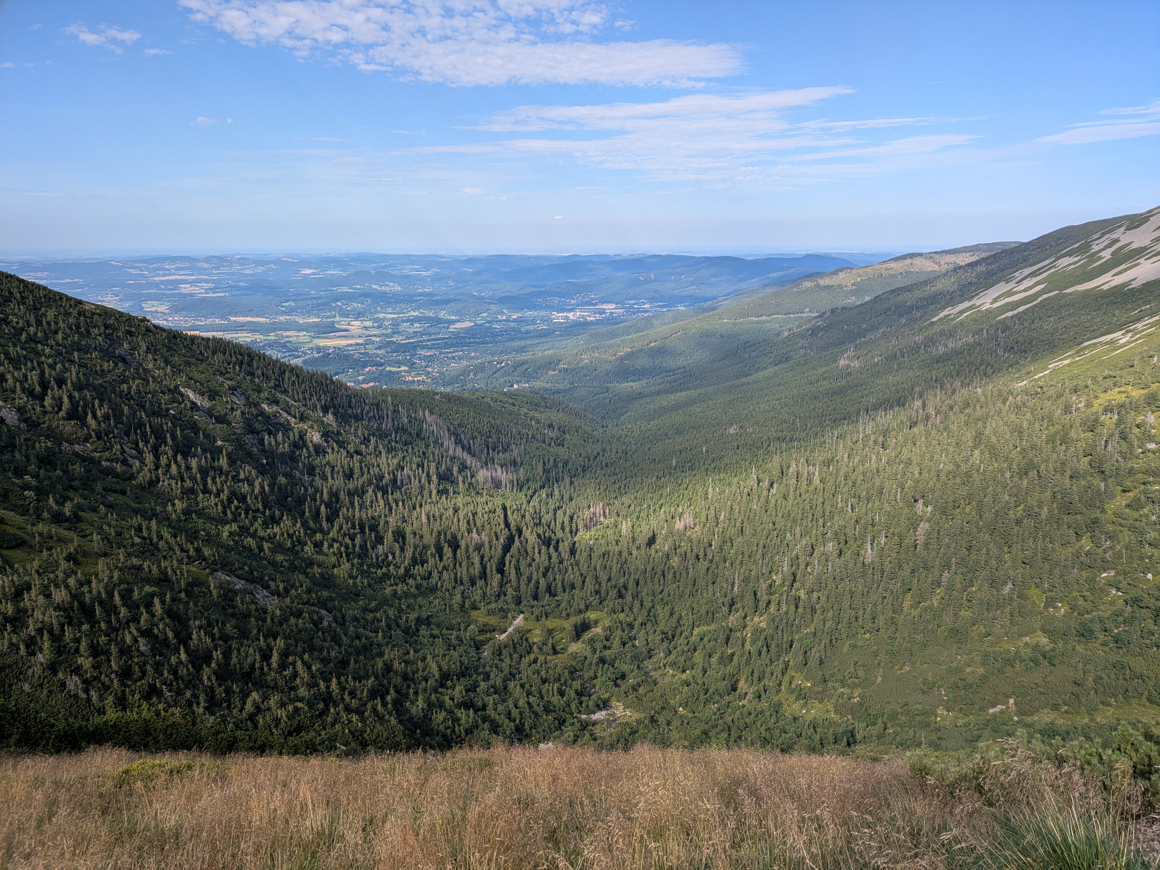
At this point, the clock was reading 17:00, we still had quite a few kilometres left to go, and the shadows were already growing longer. We had the sun at our backs and got some nice views across the Polish lowlands, plus the usual selection of rocks, more or less forested areas, and marsh lands. We reached Polana - Kotki (Katzenschlosslichtung / cat castle glade) at 18:45, and got back to Karpacz at around 20:15.
See lib.finalrewind.org/Pramen Labe for more pictures.
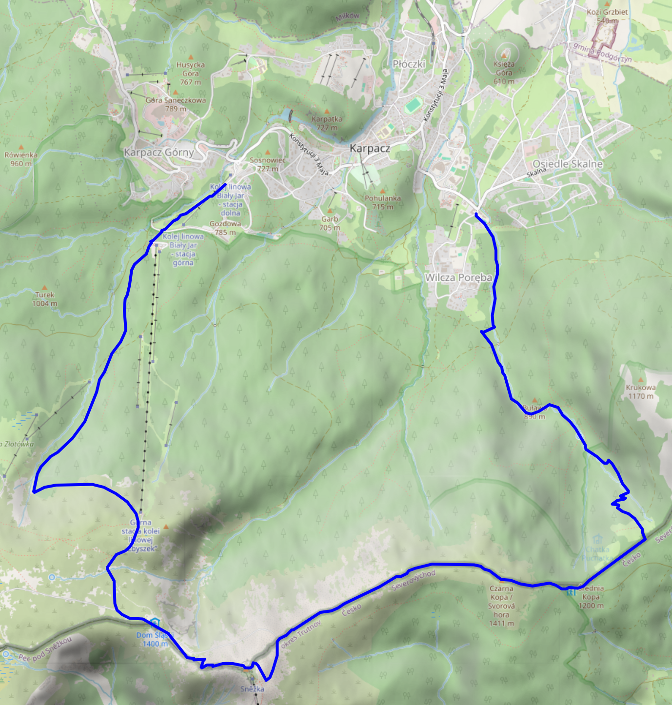
Krkonoše day 3: Malá Úpa and Tabule
This is the third of four posts about our 2025 vacation in the Giant Mountains (Krkonoše / Karkonosze), see Vacation in the Giant Mountaints for an introduction.
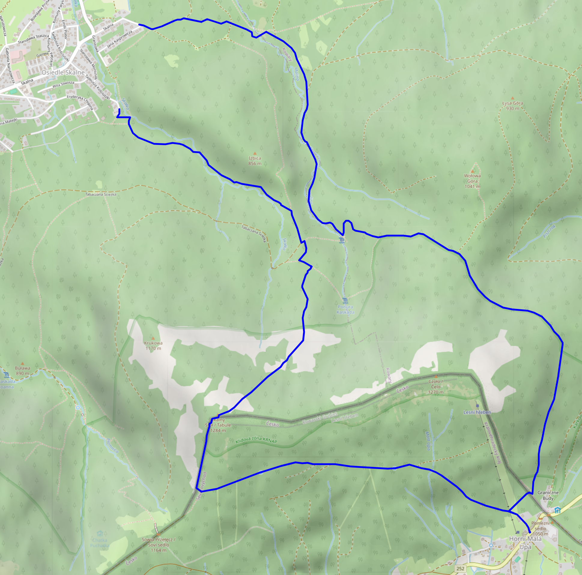
We wanted to have a change from the typical Polish food in the evening, and, thus, decided to climb up to Horní Malá Úpa on the Czech side of the Giant Mountains, have lunch there, walk a bit along the ridge, and return to Karpacz.
Ascent, Part 1
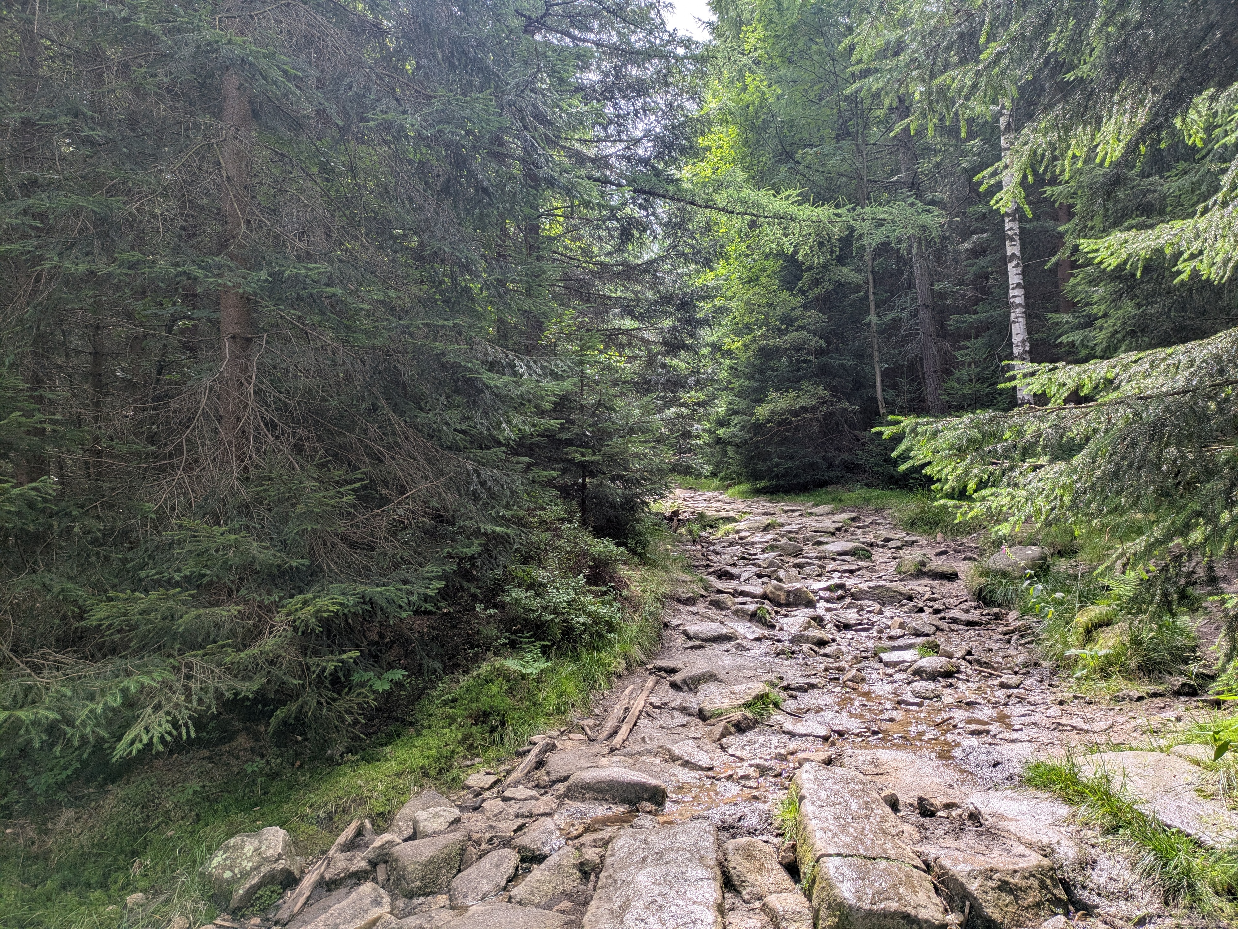
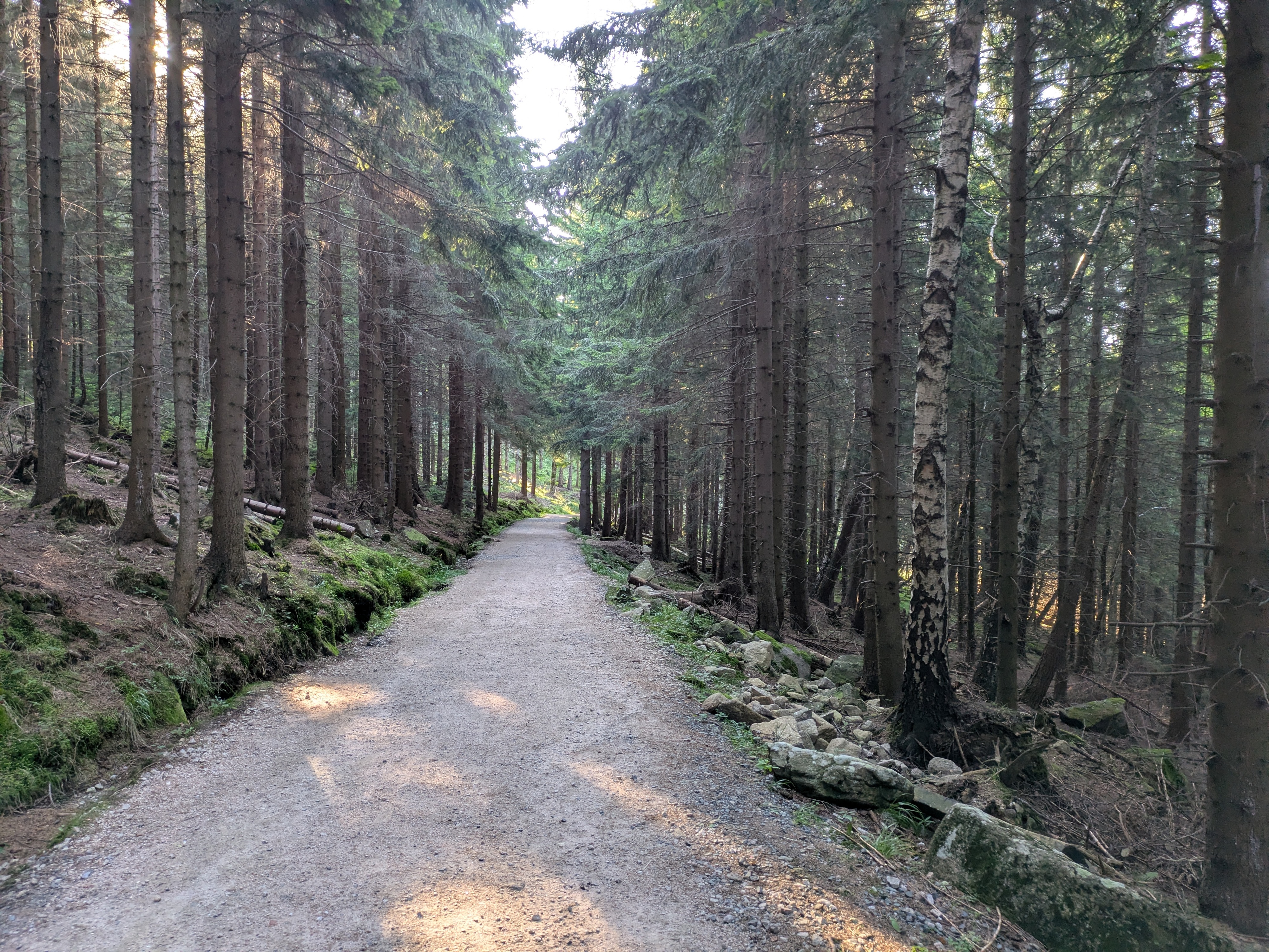
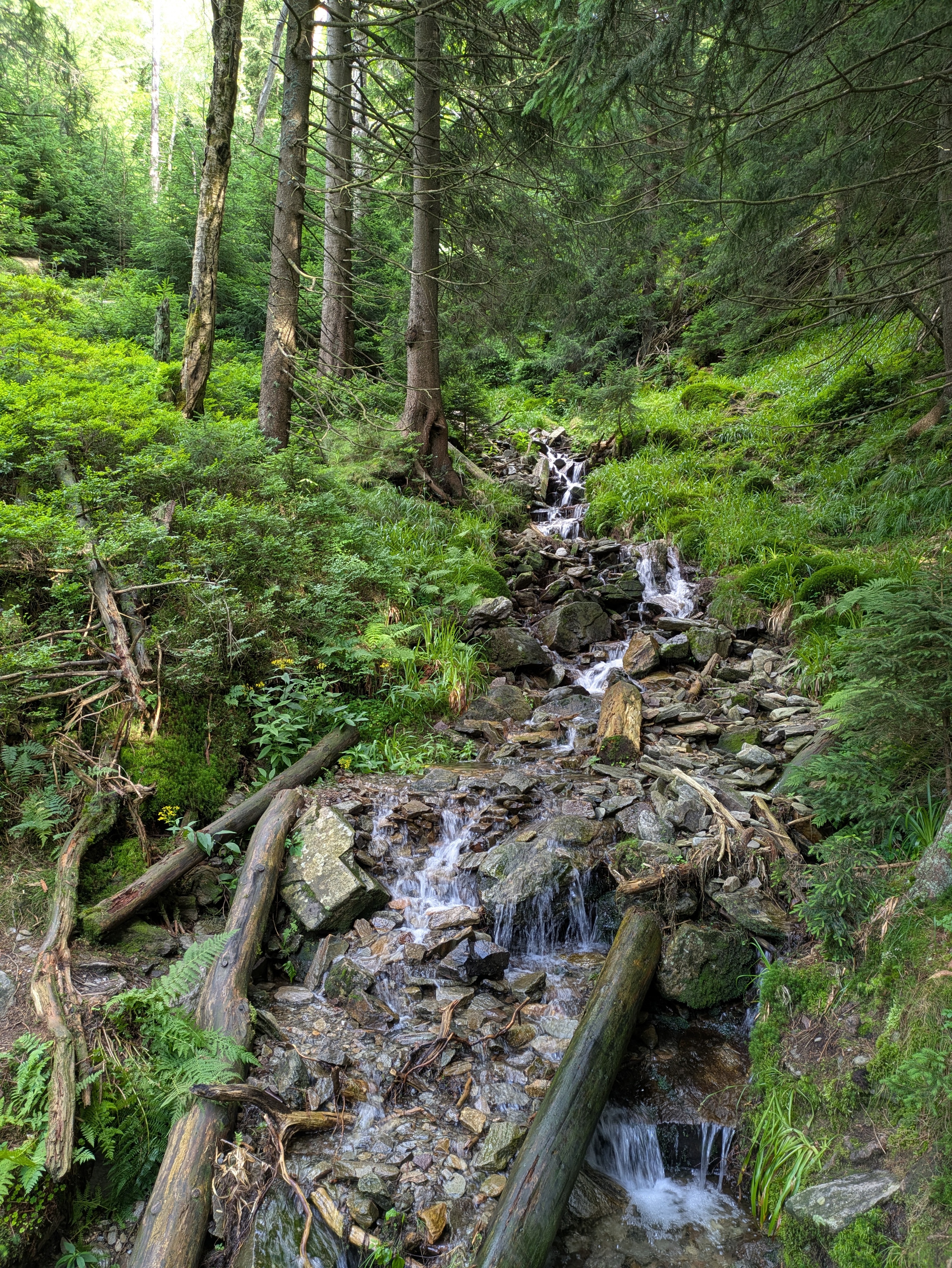
We started at around 10:30 from the very West of Karpacz, specifically its Osiedle Skalne suburb. From there, we took a path along (and, as often as not, across) the Malina stream (Langwasserbach). Some crossings came with bridges, others with broken bridges, and some with just a few strategically placed rocks. The latter parts of the path are helpfully marked with exclamation marks, likely indicating precisely these challenges. Anyhow, we enjoyed the quiet we had in this part of the forest, and made it through all fords without surprise baths.


Budniki
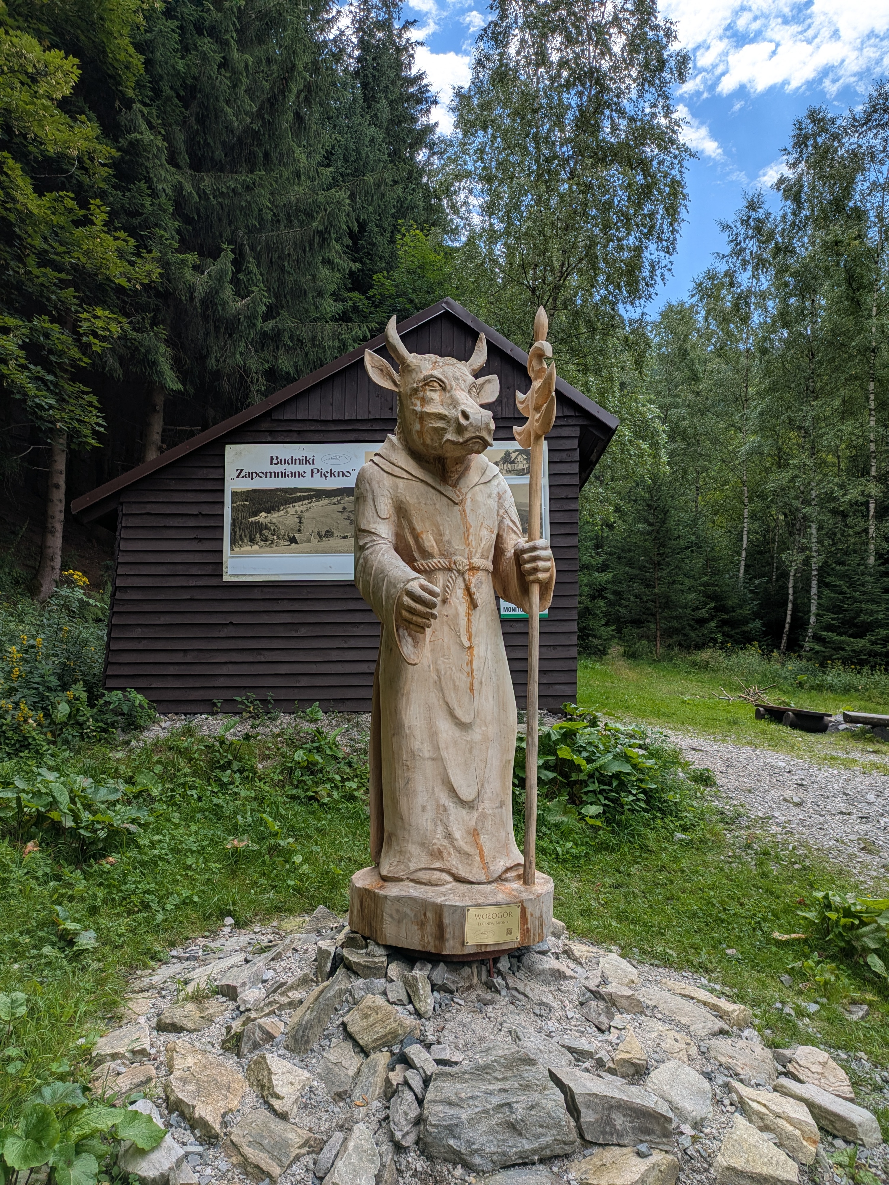
At 12:00, about a third of the way up, we reached former Budniki (Forstbauden / Forstlangwasser). We weren't aware of this site when planning the trip, so that was a pleasant surprise. Essentially, Budniki is a former settlement that, due to its location very close to the peaks of the Giant Mountains, had the peculiarity of not receiving any direct sunlight for 110 days a year. Apparently, it was abandoned around 1950 due to preparations / explorations for uranium mining operations. We also learnt about Wołogór, which doesn't seem to have an English or German Wikipedia page that I can link. Furries, they're everywhere!


We also found out that the bread we had brought along was not a proper dark bread, but simply wheat with activated charcoal. That's the kind of surprises you can get when you aren't fluent in Polish.
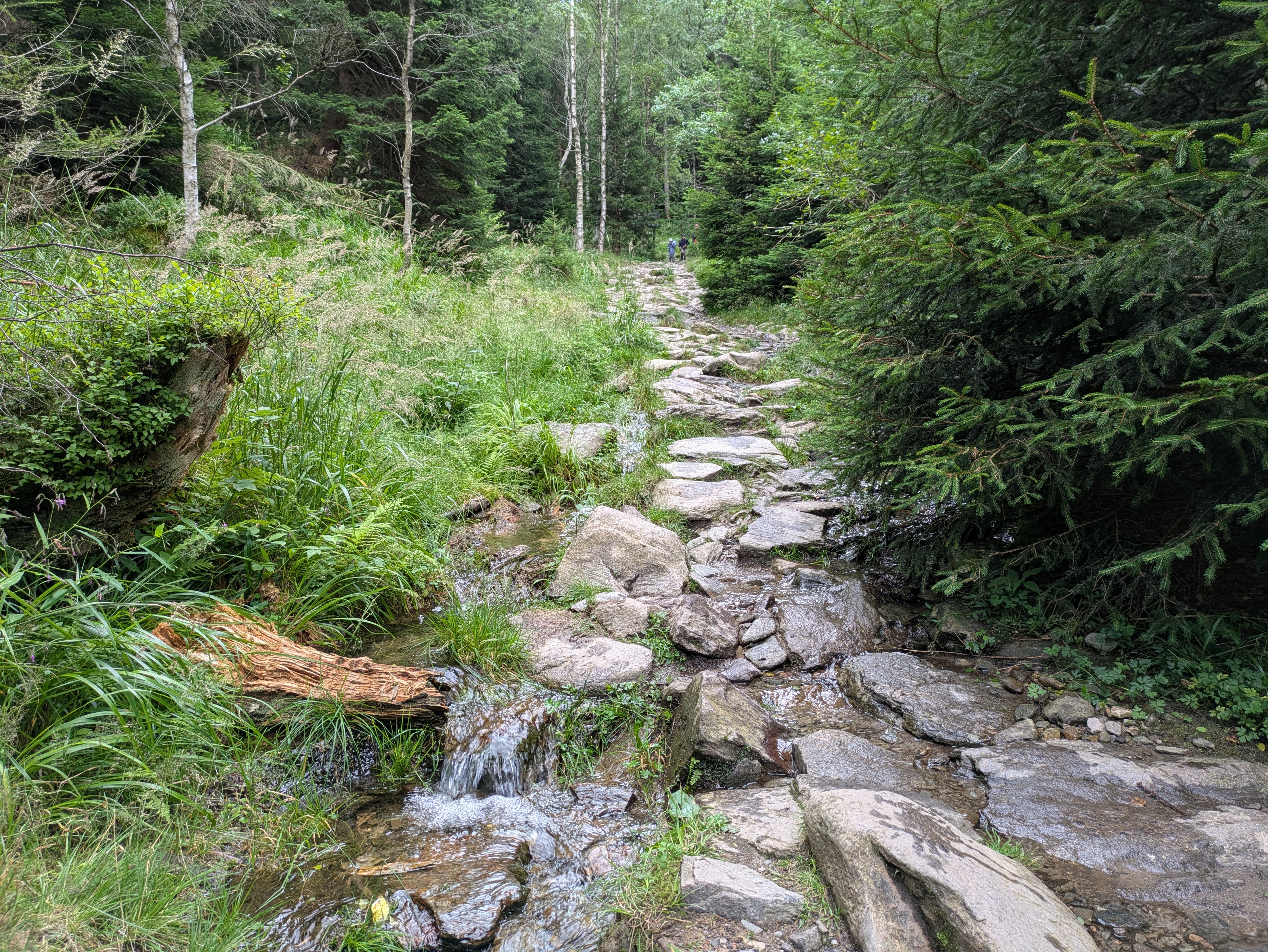
Ascent, Part 2
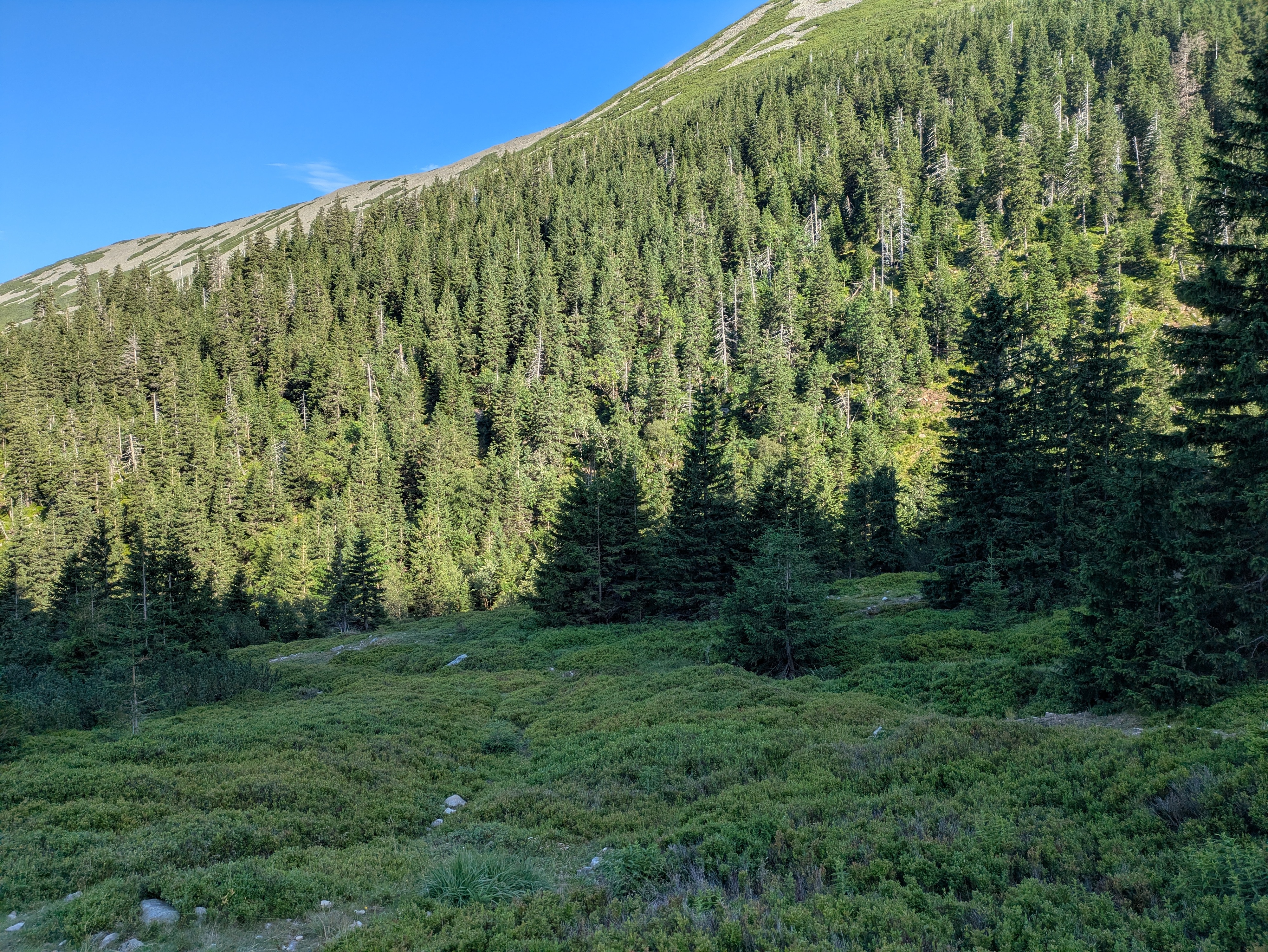
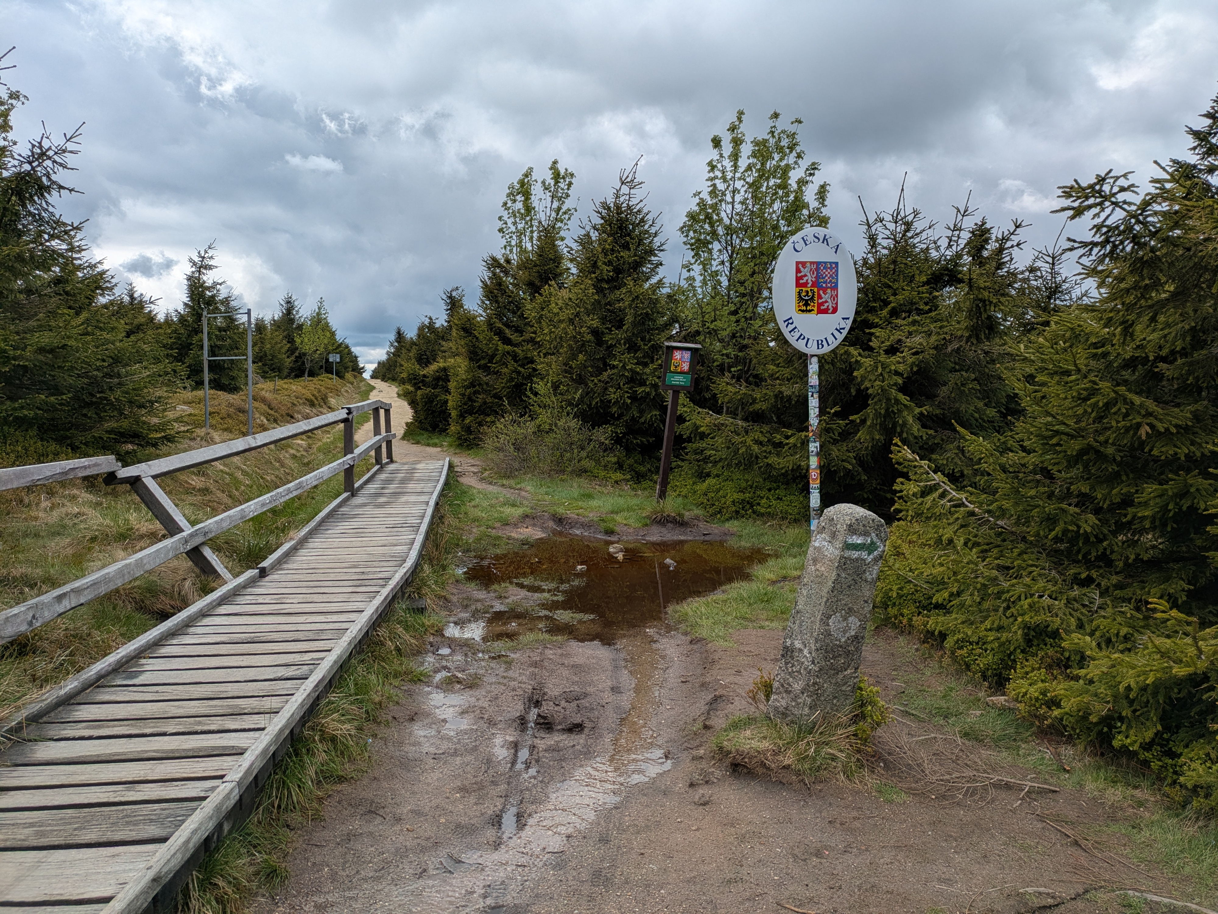
From Budniki on, the remaining 400-or-so metres of elevation got quite challenging, with uneven and pretty steep terrain that just kept going on and on. When we finally reached a more even path close to the ridge line, we were greeted with the usual occasional flooding, lush green, and (at about 14:00) a sign welcoming us to Česká Republika.


Horní Malá Úpa
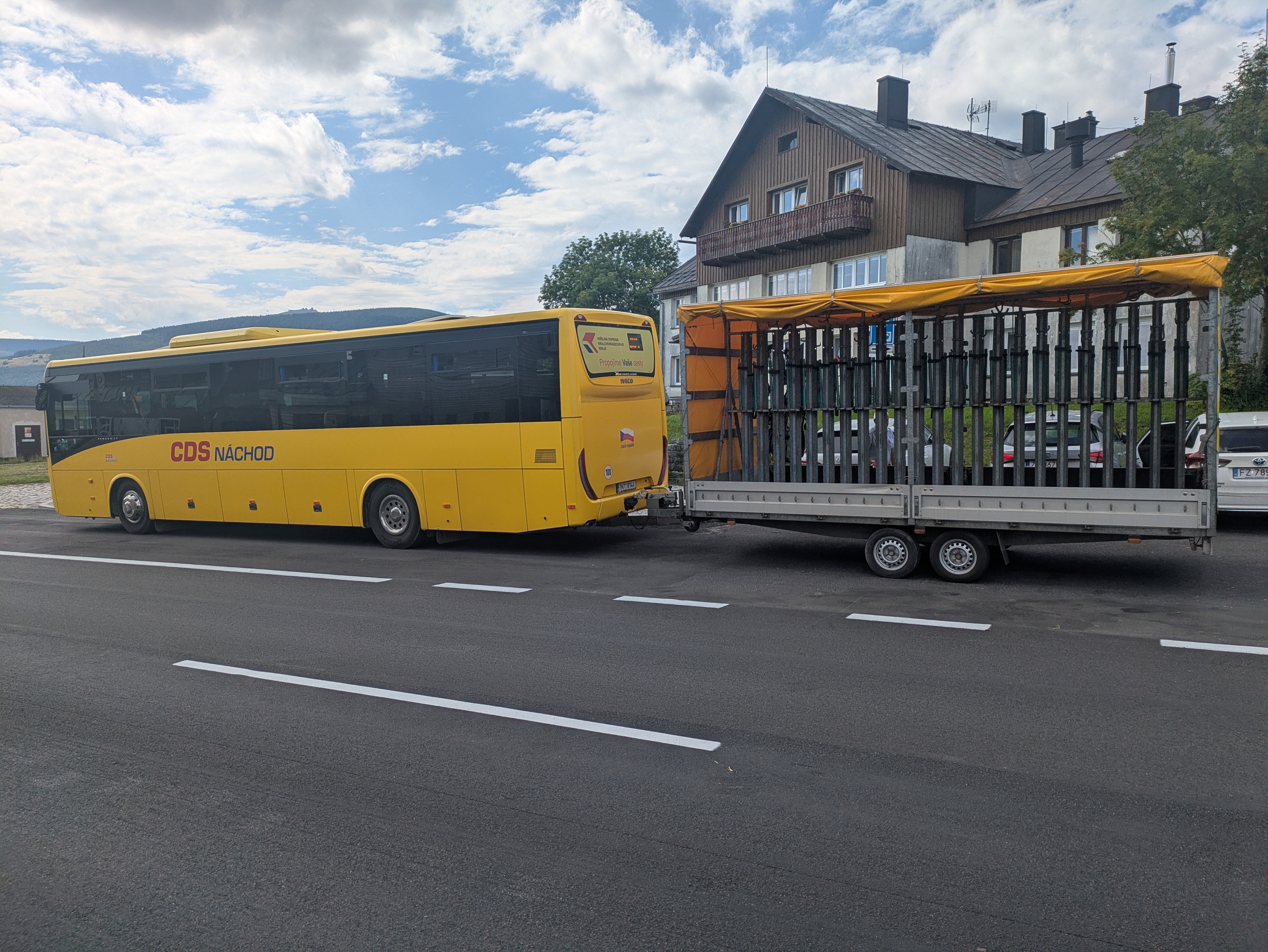
For English speakers, the jokes related to the name of Horní Malá Úpa (Ober-Kleinaupa / upper Malá Úpa) write themselves. So naturally, we had to pose for the obligatory photos near the entrance sign. Apart from that, the municipality is unspectacular. There's some border stones that still bear markings of the former ČSSR (Tschechoslowakei), some skiing infrastructure, and buses that are specifically outfitted for taking on bikes (or, possibly, skis). We had lunch at Pivovar Trautenberk, which I can recommend. Also, the nice part about Česká is that if you order lemonade, there's a high likelihood that you'll be served kofola 😋.


Tabule
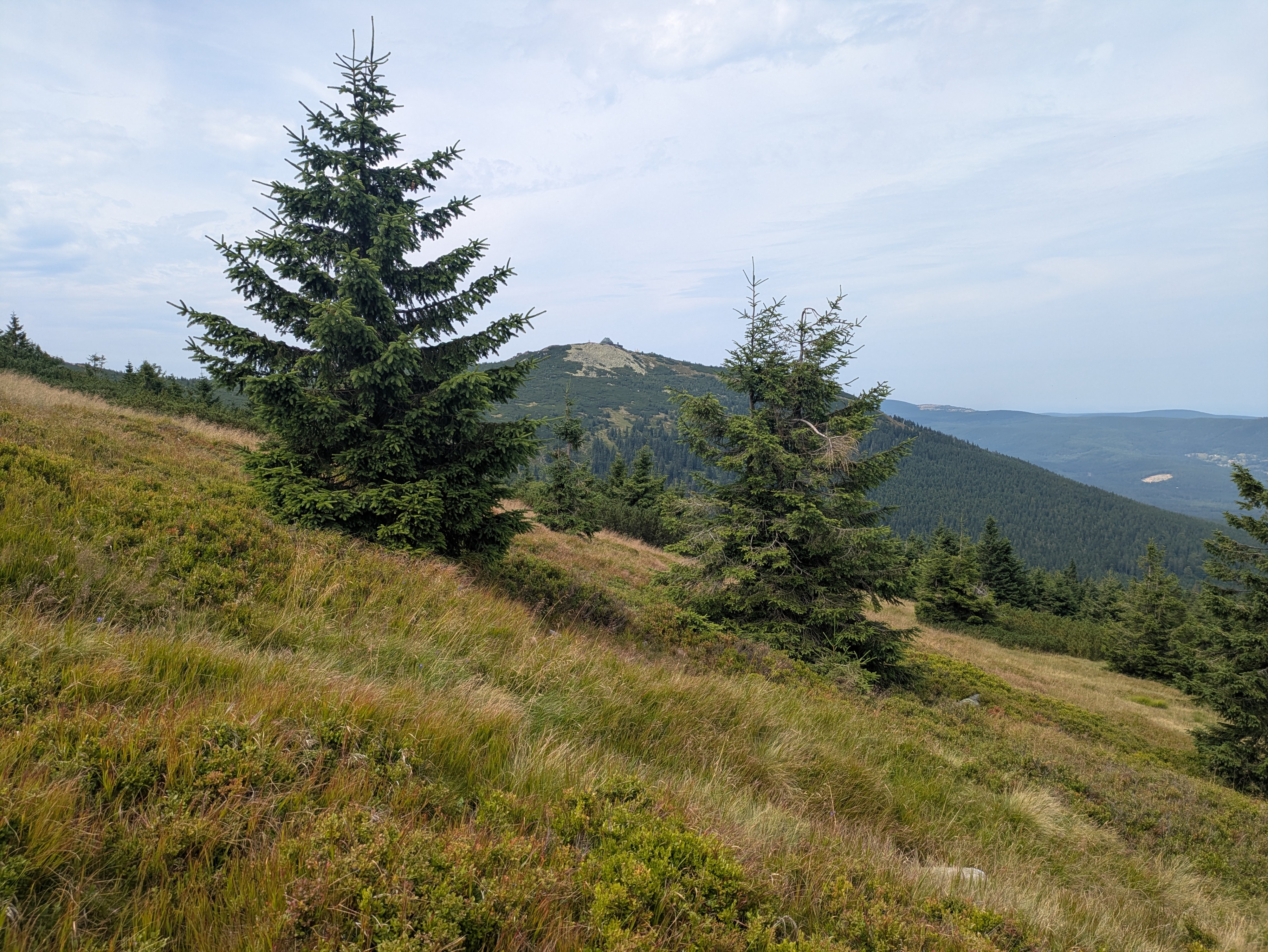
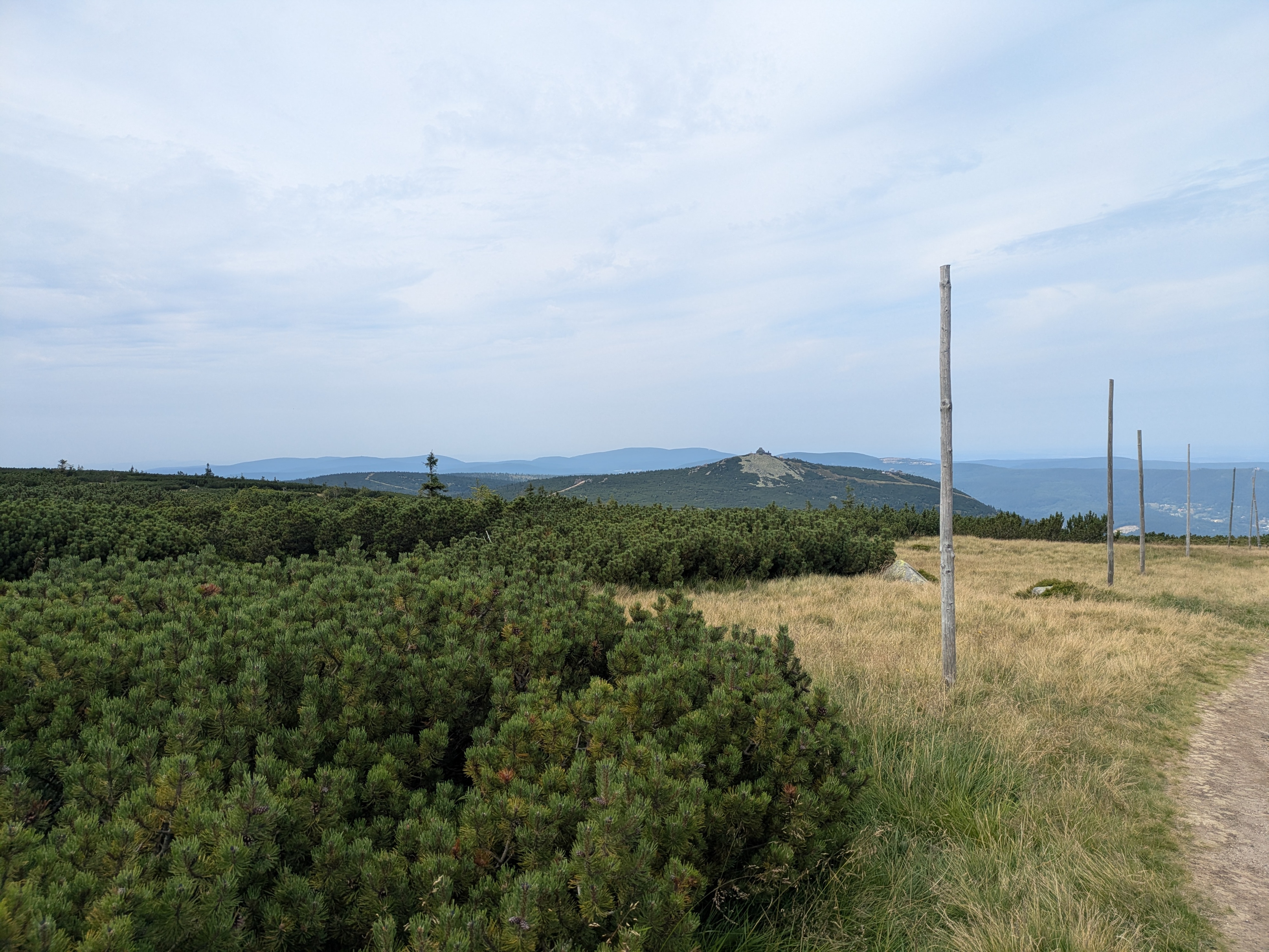
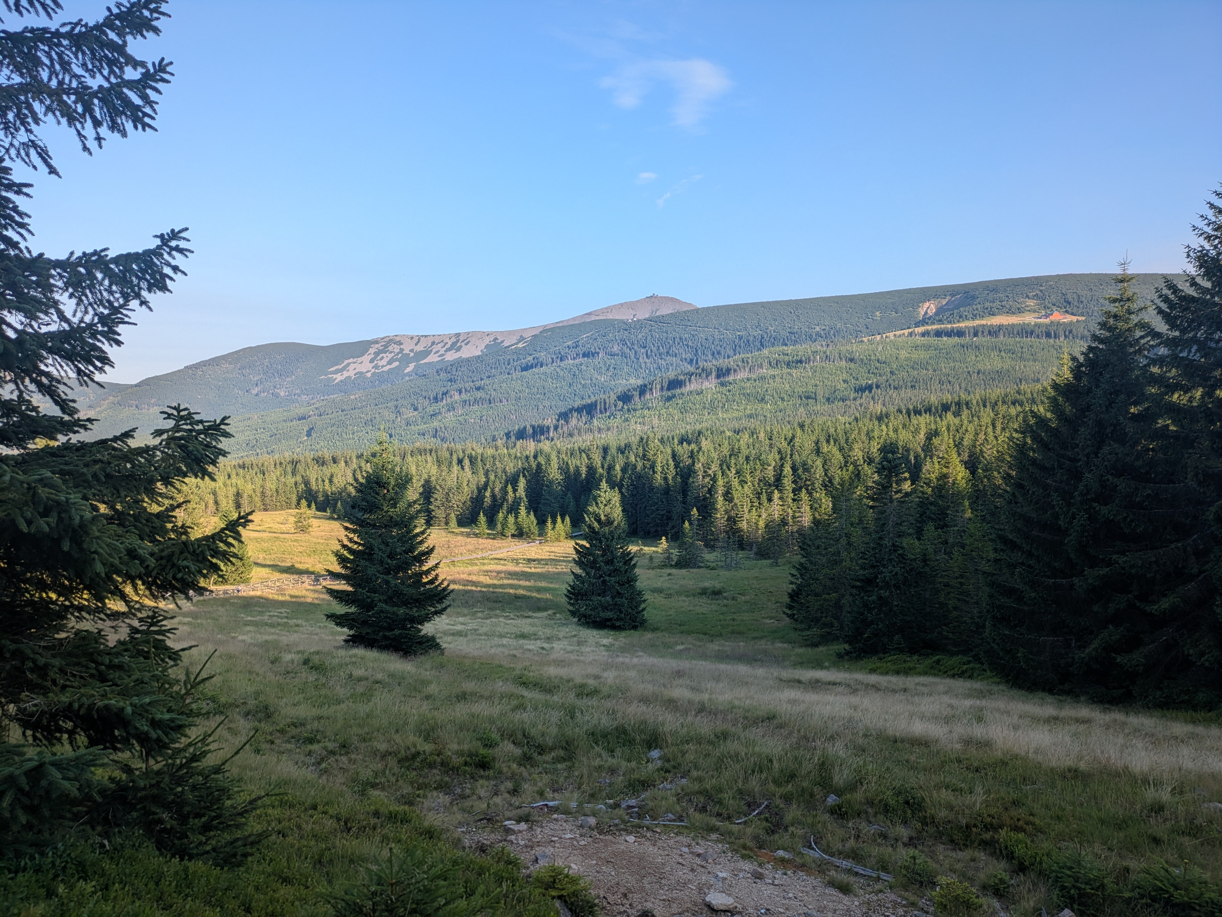
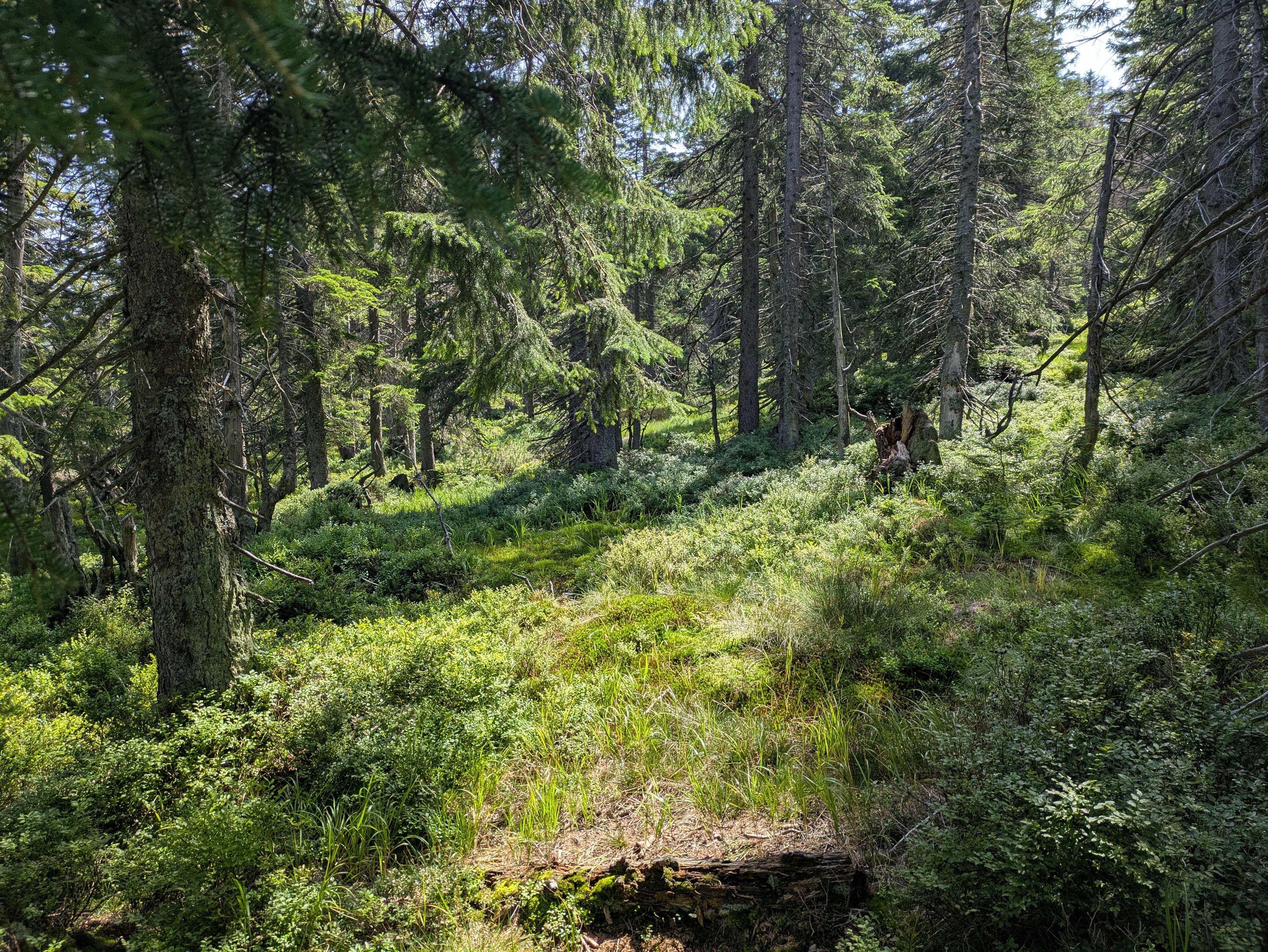
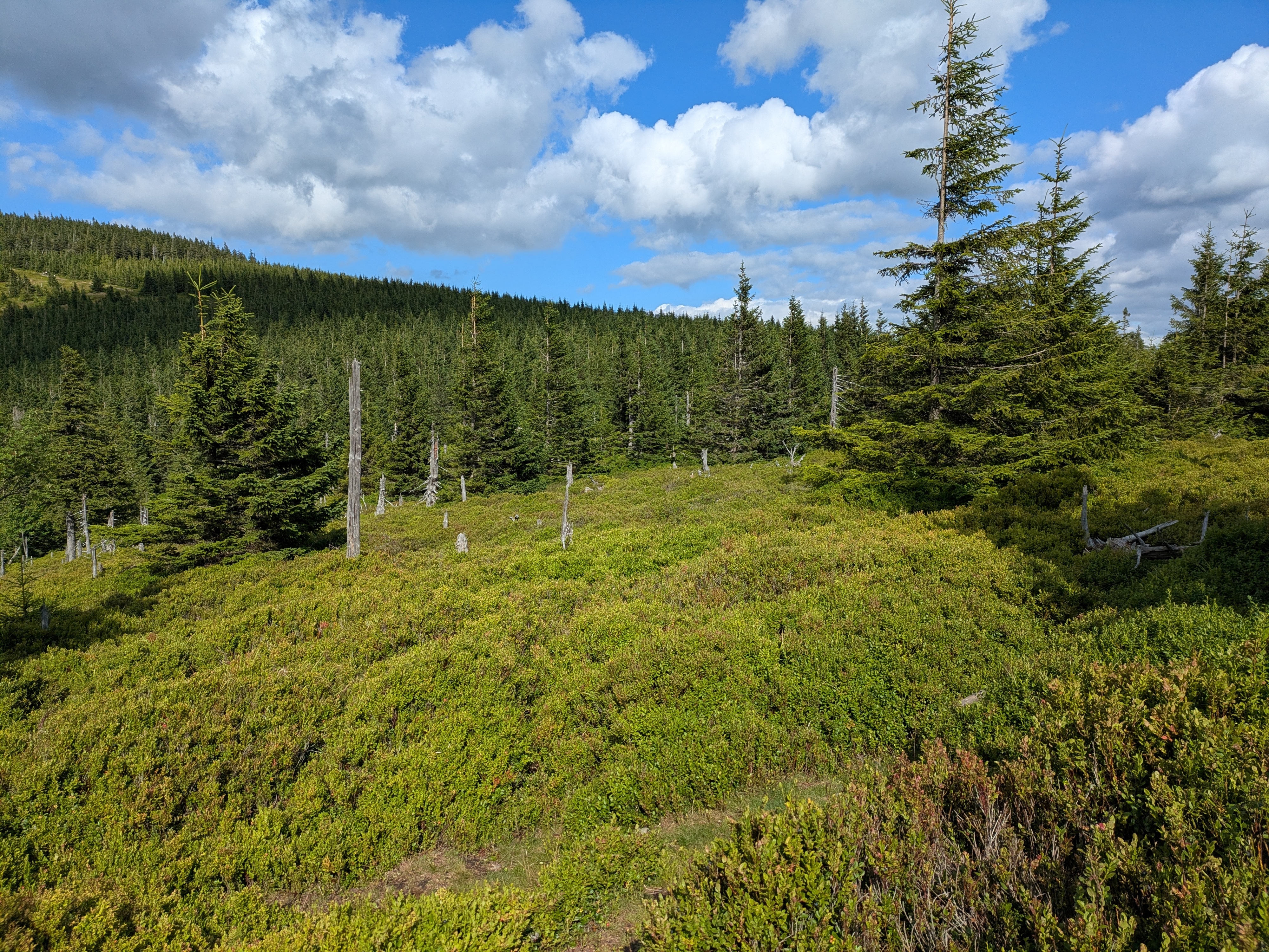
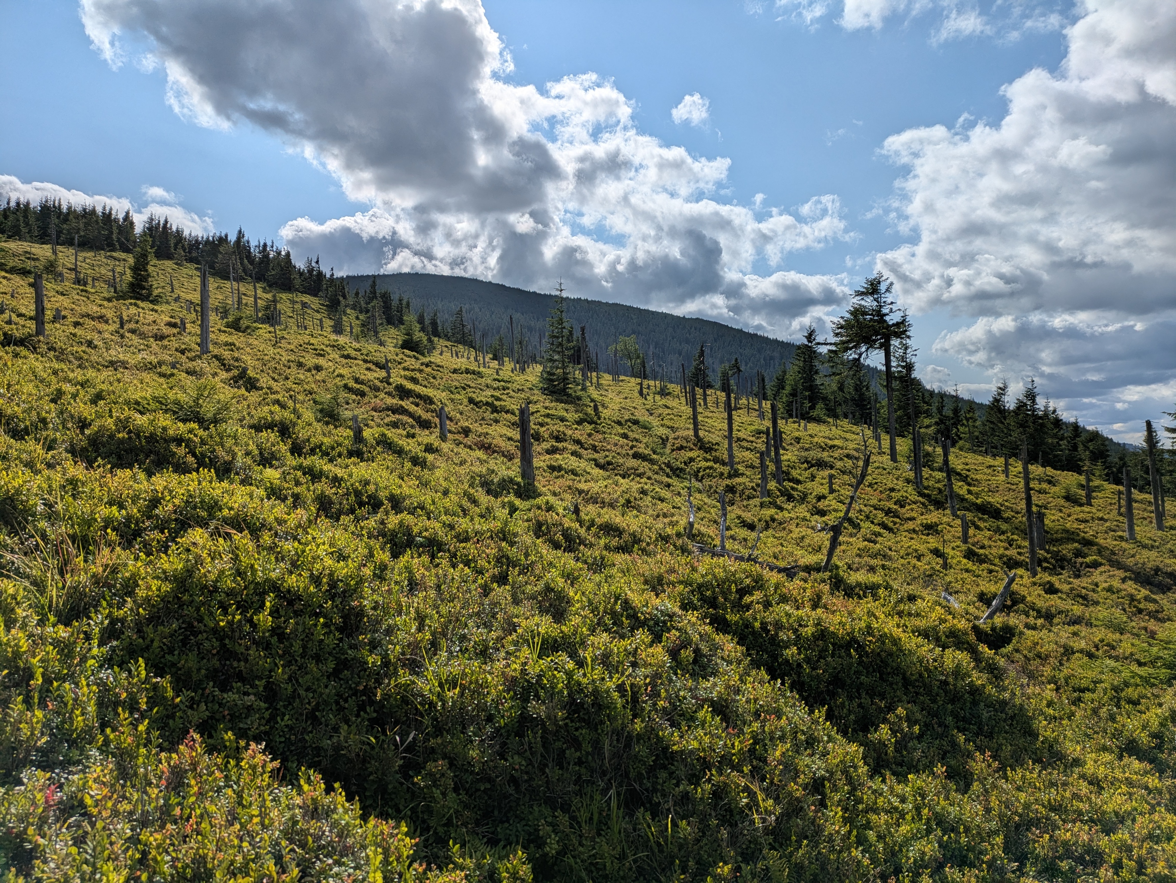
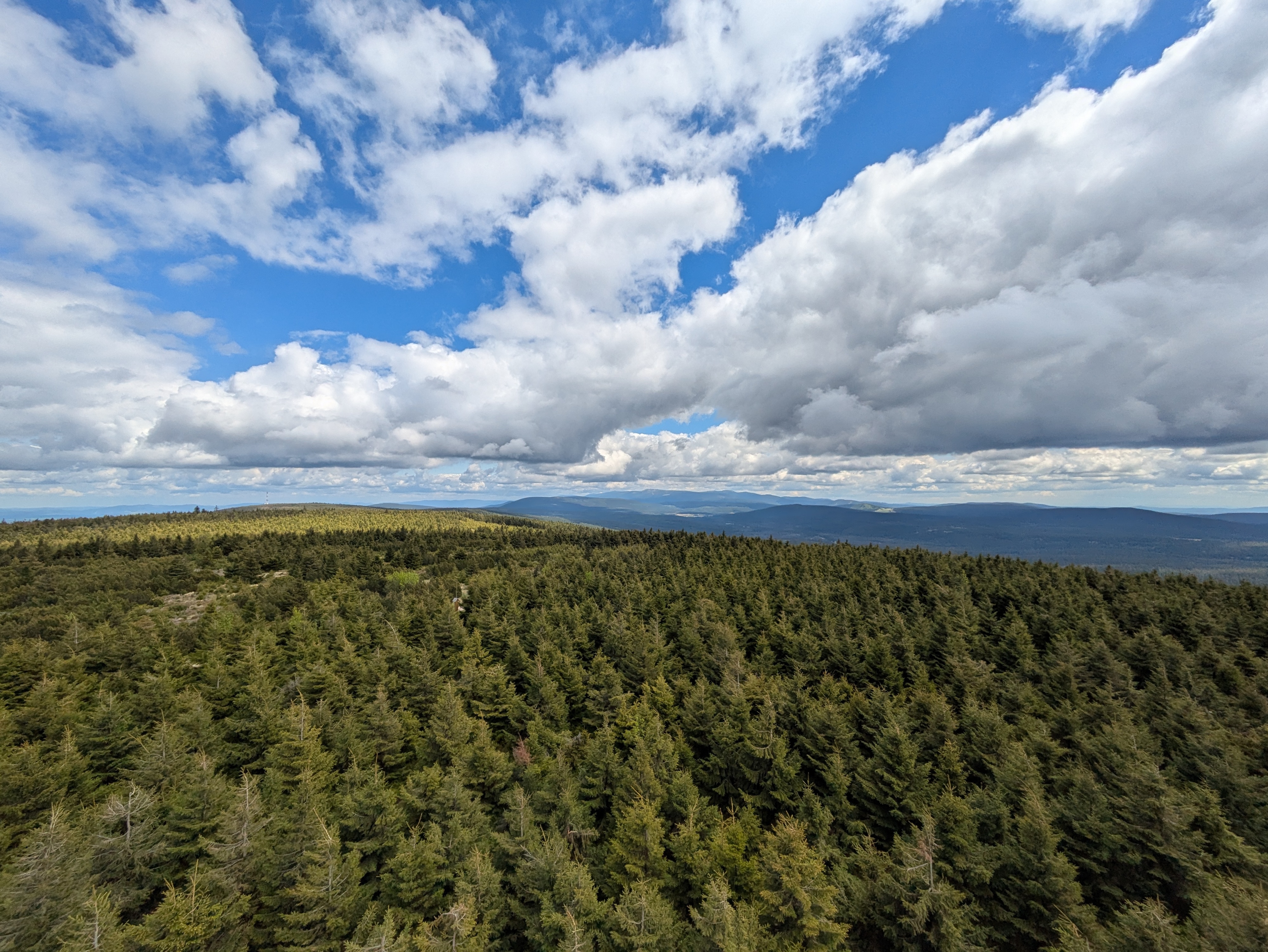
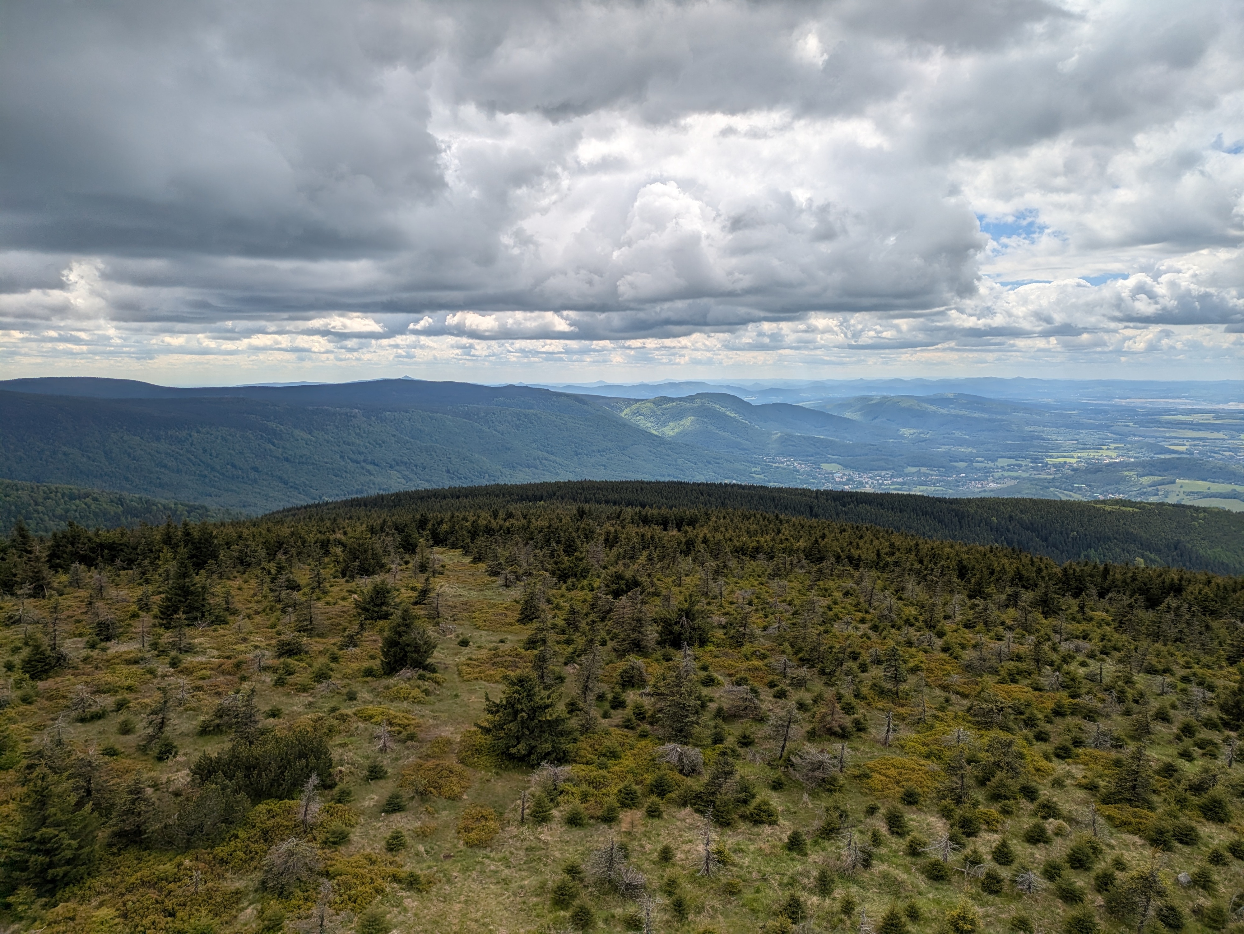
After some exploration and our lunch break, we left Horní Malá Úpa for the final climb up the nearest peak at around 15:30. We started out in a dense forest, and then, as the vegetation grew thinner, got some views towards other parts of the Giant Mountains.

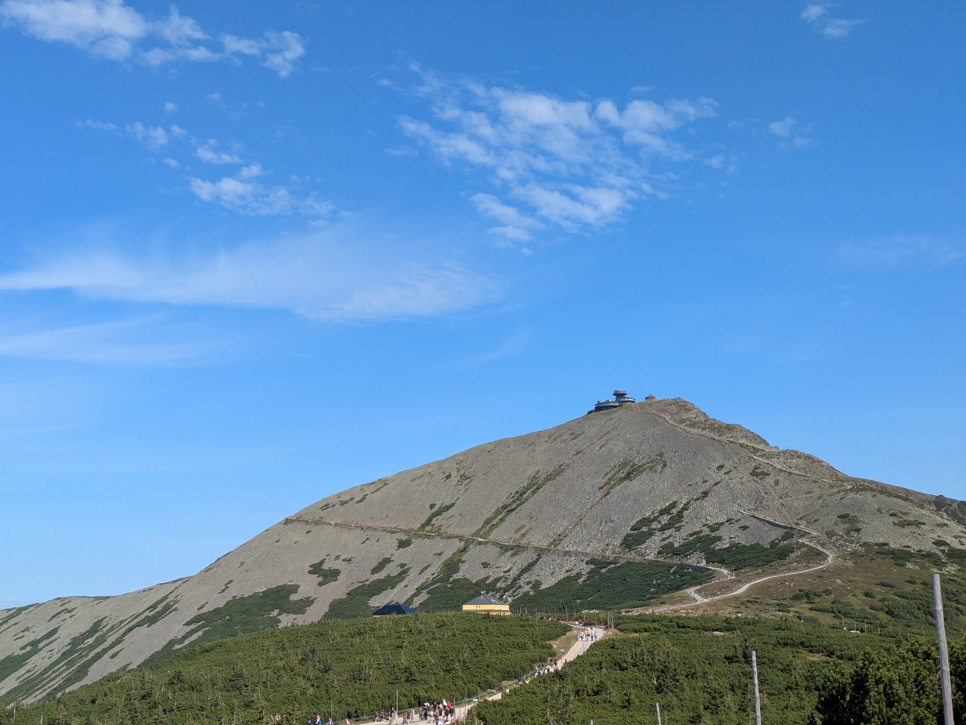
We reached Tabule (Tafelstein / table peak) at about 17:00, and took in some more scenery. Once again, we could spot Sněžka in the distance, and also a little bit of Karpacz and the Polish lowlands.

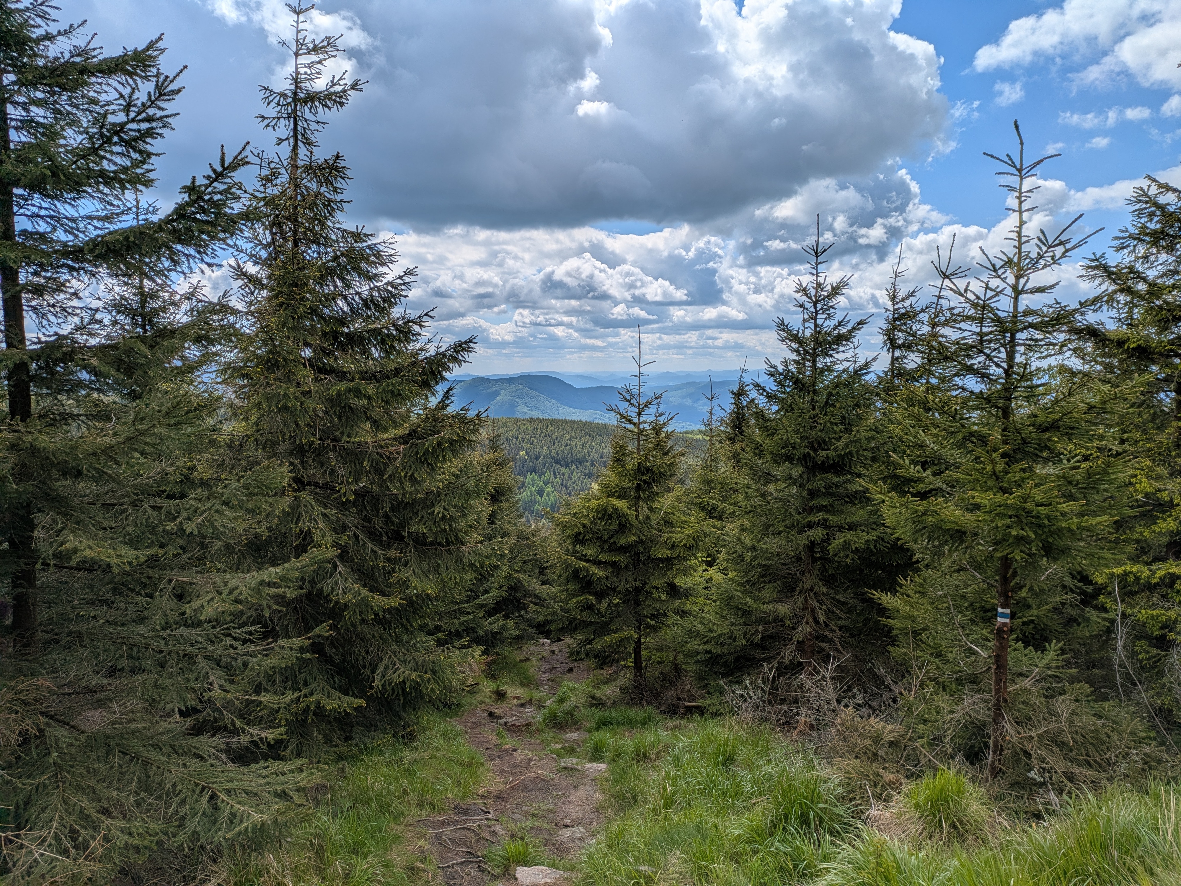
Descent
The descent took us slightly west of the path we used for the ascent, and was just as steep. It also really drove home just how much its height (and, likely, other factors) affect the vegetation – we got everything from low bushes to coniferous and birch forests.


We passed Budniki once more, and then followed the Skałka stream for a bit. Here, we were faced with another surprise: a (possibly carbonated) spring that not even OpenStreetMap knew about.


We got back to Karpacz at about 19:00. As usual, more photos are available at lib.finalrewind.org/Tabule 2025.
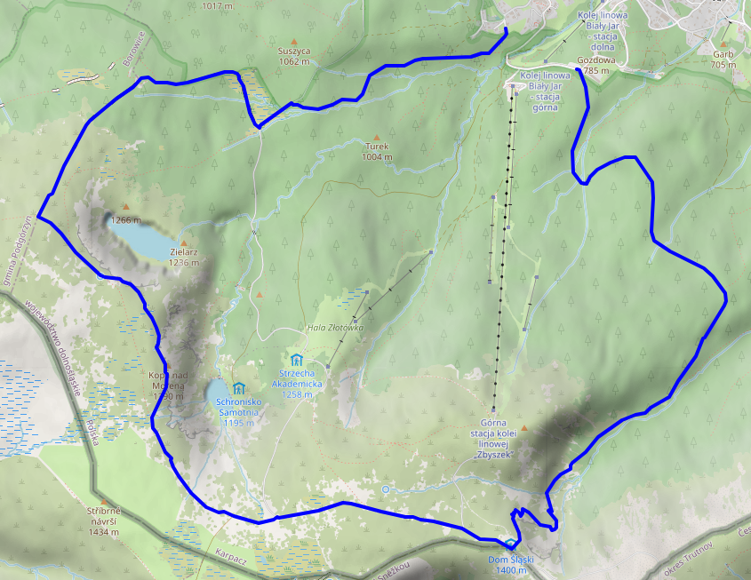
Krkonoše day 2: Słonecznik: Wetlands, Stones, and Ponds
This is the second of four posts about our 2025 vacation in the Giant Mountains (Krkonoše / Karkonosze), see Vacation in the Giant Mountaints for an introduction.
On this day, we decided to make our ascent more to the east, take a look at the wetland we'd find there, and then see where our intuition took us.
Ascent
We started at around 11:00 from Karpacz Górny (“upper Karpacz”) and followed a path along the Pląsawa stream towards the wetland near Polana - Kotki (Katzenschlosslichtung / cat castle glade). The path along the stream is steep, but relatively even, and the stream provides a nice background soundtrack to the ascent. Right before Polana - Kotki, we merged with the (decidedly more crowded) main track towards Sněžka, and passed a KPN employee who glanced at my smartphone to verify that we did indeed have KPN tickets. Luckily, most of the crowd continued to Sněžka, whereas we left the track to the east, right into a small patch of wetland.
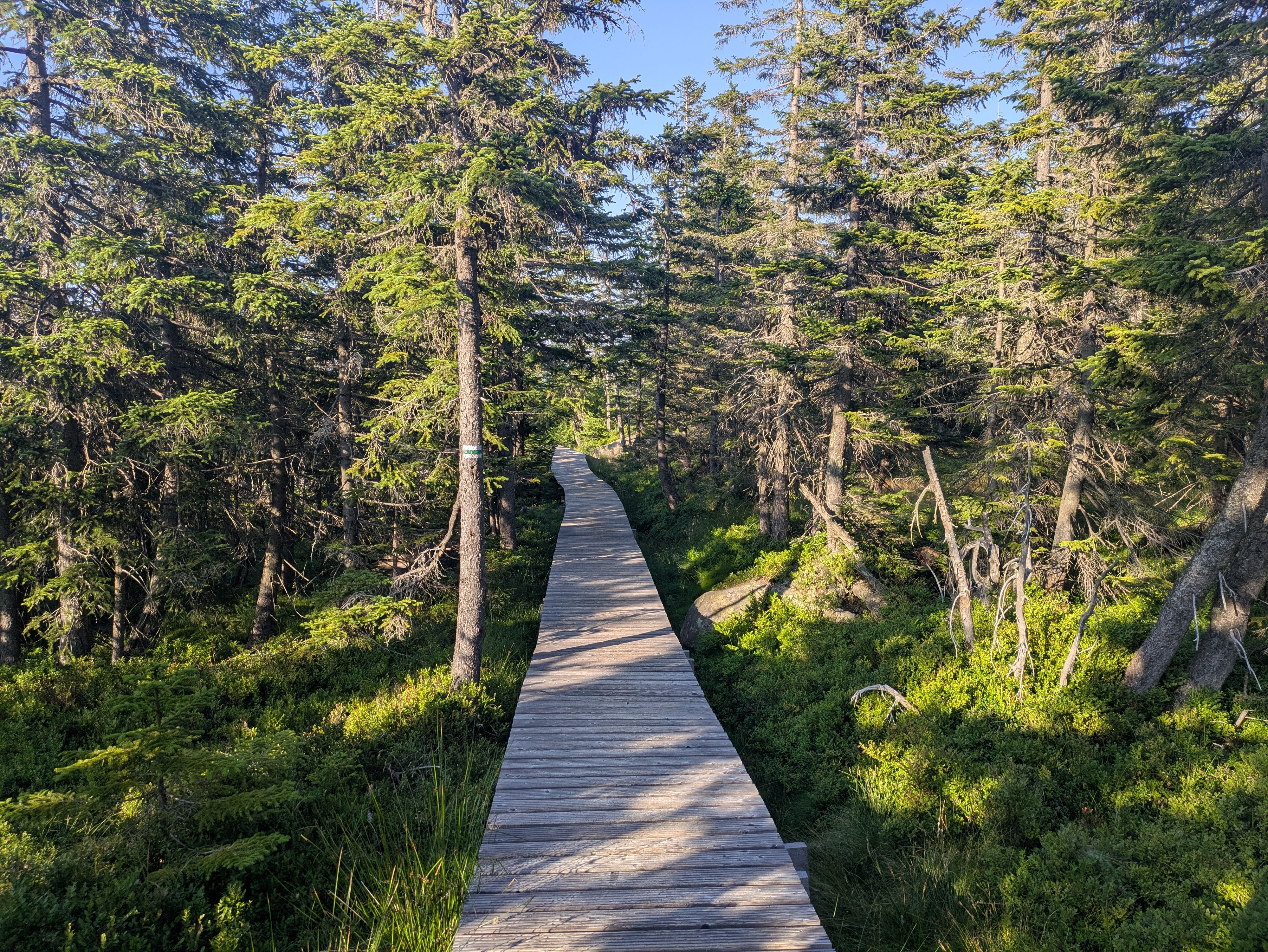
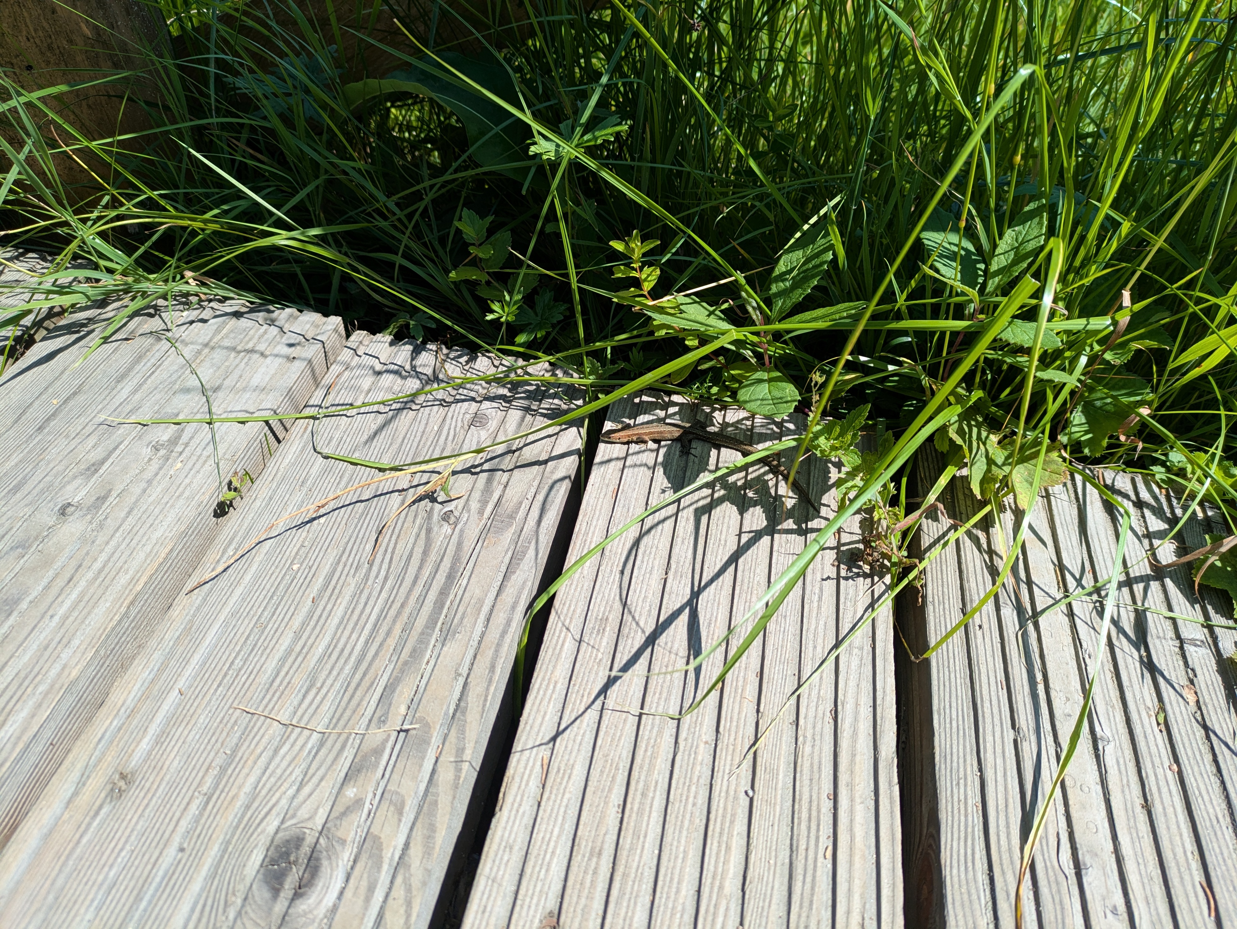
Wetlands
It's a wet, grassy and relatively plain area that seems to be fed exclusively by ground water. I don't quite know whether it's a fen, bog, or marsh, but probably something along those lines. There's the usual elevated wooden walkways to help you traverse it, and already some nice views across the mountainside. We also found a lizard who was enjoying the sun :)
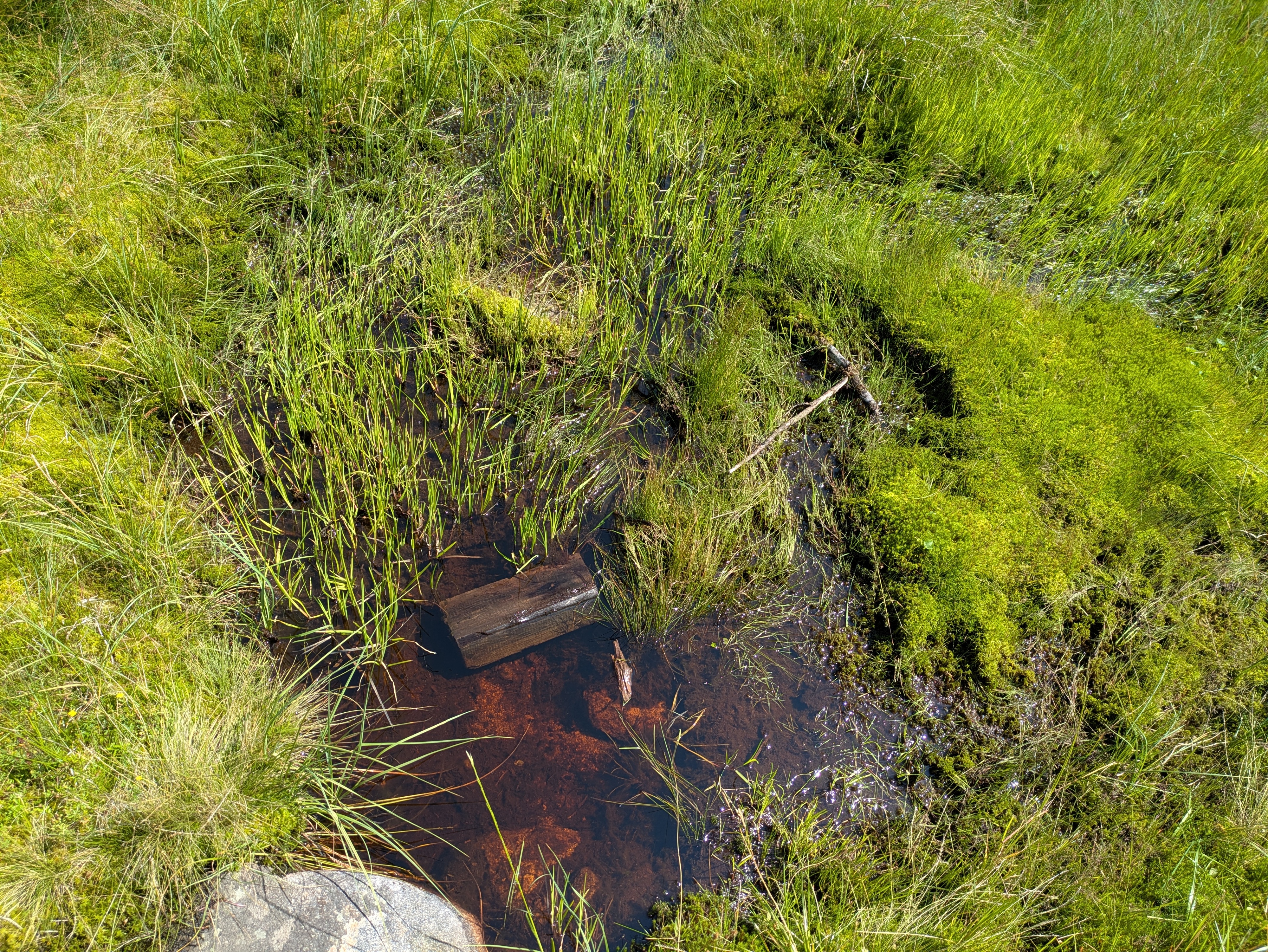
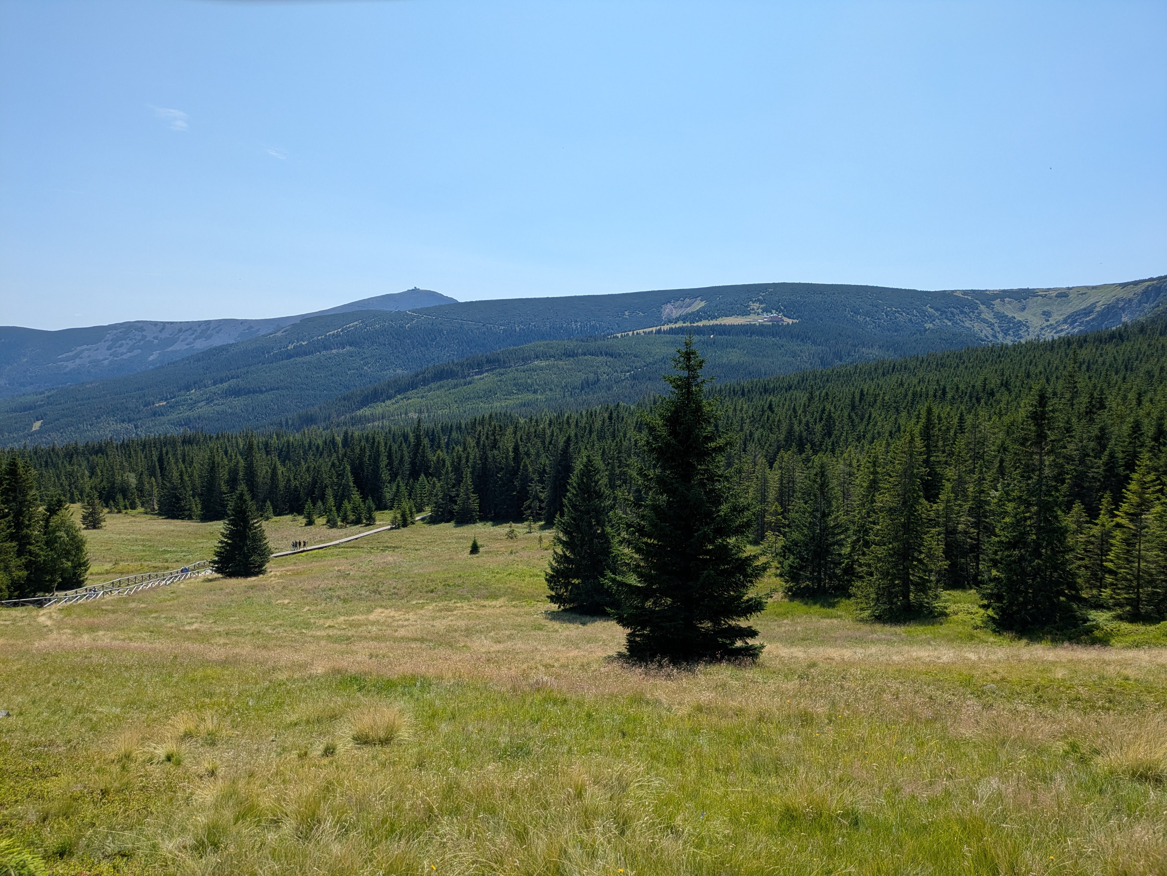
Stones
We followed the path towards the ridge of the mountain range, and passed quite a few notable granite structures. The path itself also grew more rocky and uneven, interleaved with wooden walkways that were decidedly in disrepair, featuring frequent occurences of broken or missing planks. It's a good idea to look where you're going, and not just take in the (gorgeous as usual) nature around you.
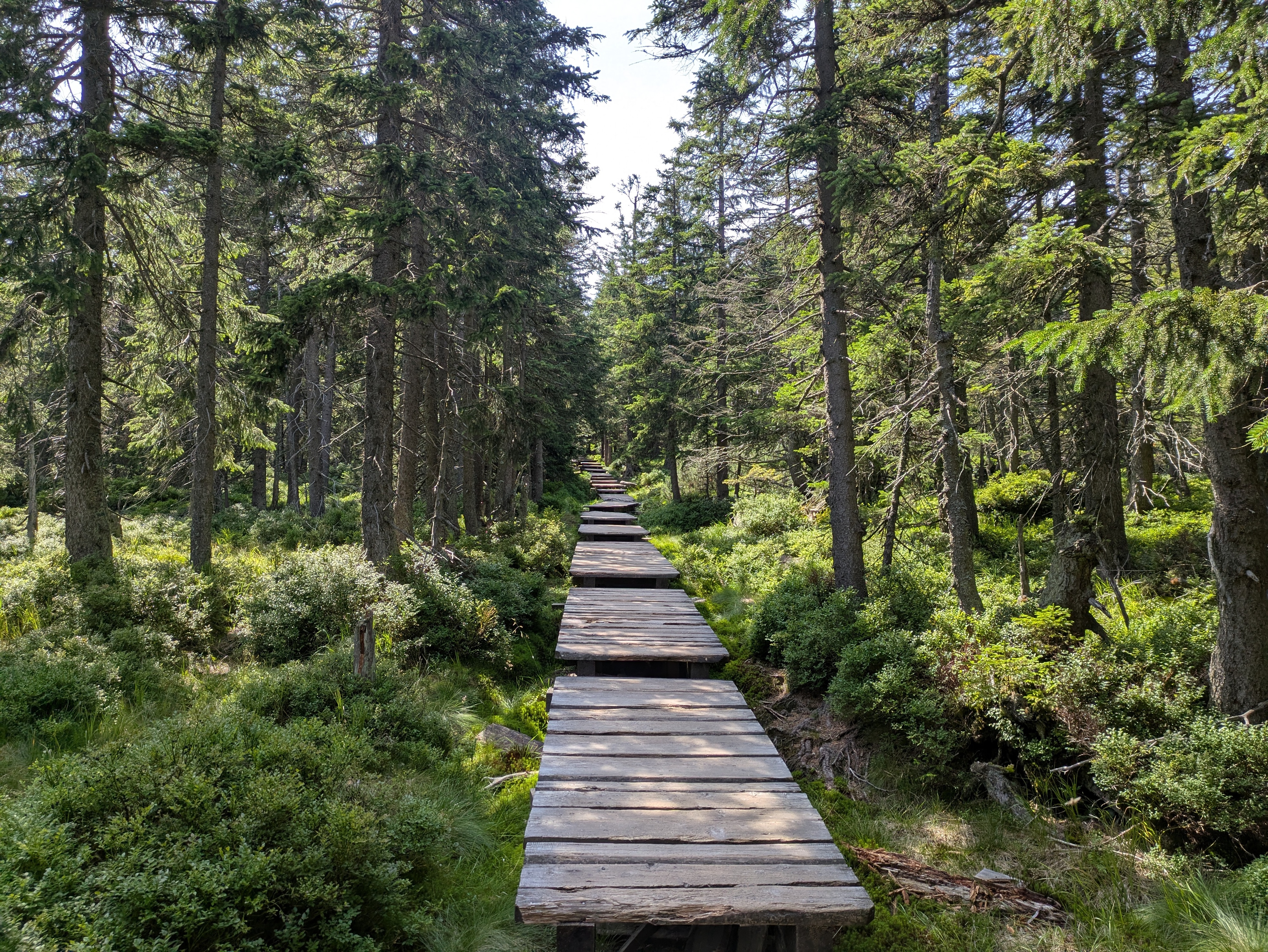
The first stone formation we passed were the Pielgrzymy (Pilgersteine / pilgrim's stones), with views towards Koci Zamek (Katzenstein / cat rock) below and Słonecznik (Mittagsstein / sunflower or noon rock, depending on whether you translate from Polish or German) above. One of them is apparently open for climbing, and if you do find a reasonably safe path up one of its plateaus, you are rewarded with a pretty nice view.
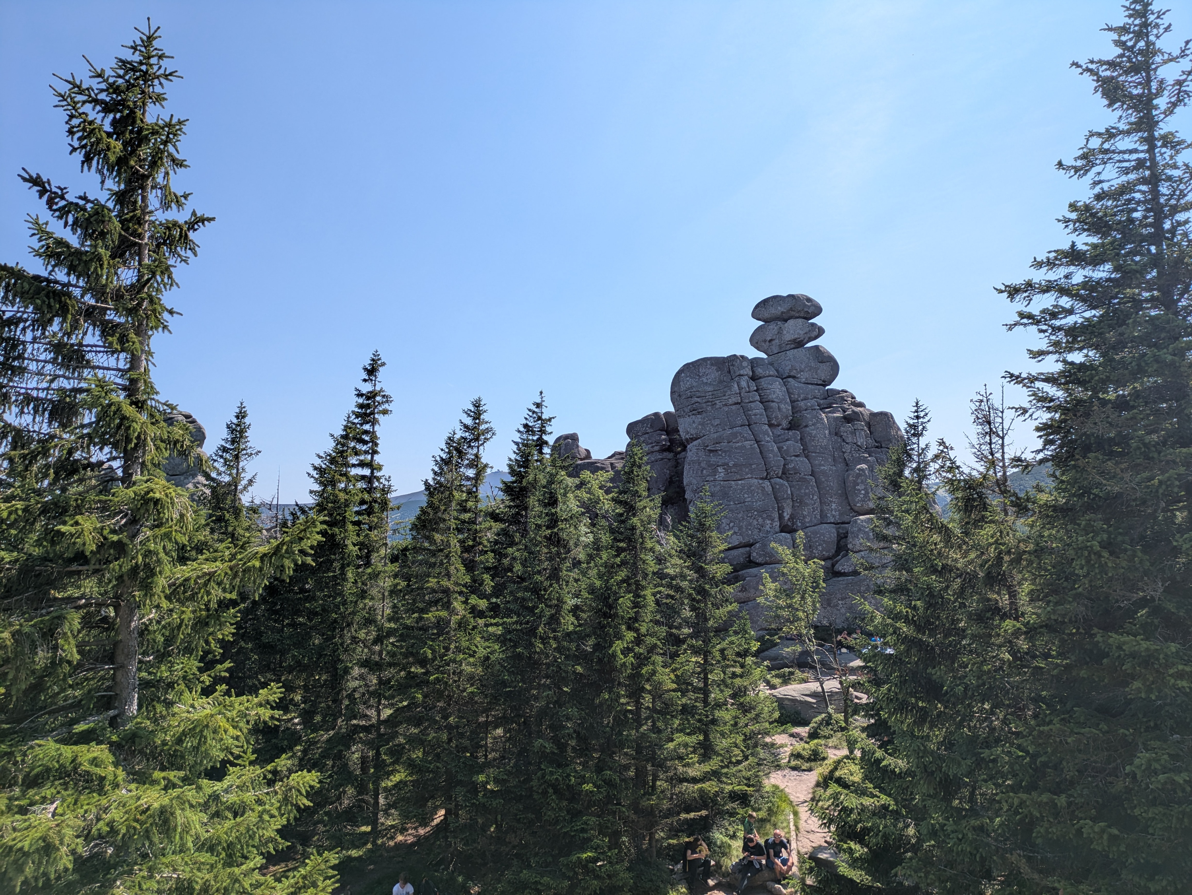
Going up further, we reached Słonecznik at around 15:00, but not before enjoying some more views down towards the valley. As Słonecznik itself was a bit crowded (though far less than Sněžka on the day before), I don't have any photos of it – see the Wikipedia link above for two samples. Just like Sněžka peak, it's also a good spot for some radio range tests, so we stayed for a bit.


Ponds
Słonecznik is also where the path up the ridge terminates, and you get to decide whether you want to take on the summits to the east or to the west. We opted for the east, which would lead us back towards Sněžka and Karpacz. As on the day before, the local groundwater frequently found its way onto the path. Apart from that, the path was relatively even, relatively easy terrain, and not too crowded. This seems to be a rather tame segment of the Krkonoše ridge line.

Before too long, we ended up above Wielki Staw (Großer Teich / large pond) and, a bit later, Mały Staw (Kleiner Teich / small pond). The water was quite calm, clear, and full of rocks that had fallen into it over time.


Descent
We decided to make our descent at Dom Śląski (Silesian house), a tad eastwards of the path we used for our ascent on the day before, hoping that it'd be less crowded. But before that, we got yet another view of Sněžka, which also seemed slightly less crowded than the day before – possibly because it was already quite late in the day (around 16:30), and the shadows were already growing longer by the minute.
Our descent took us from Dom Śląski down into the Kocioł Łomniczki (Melzergrund) valley, right along the Główny Szlak Sudecki (Sudeten-Hauptwanderweg / Main Sudetes Trail). Kocioł Łomniczki valley is a former glacier site, and as such the path starts out very steep and rocky.
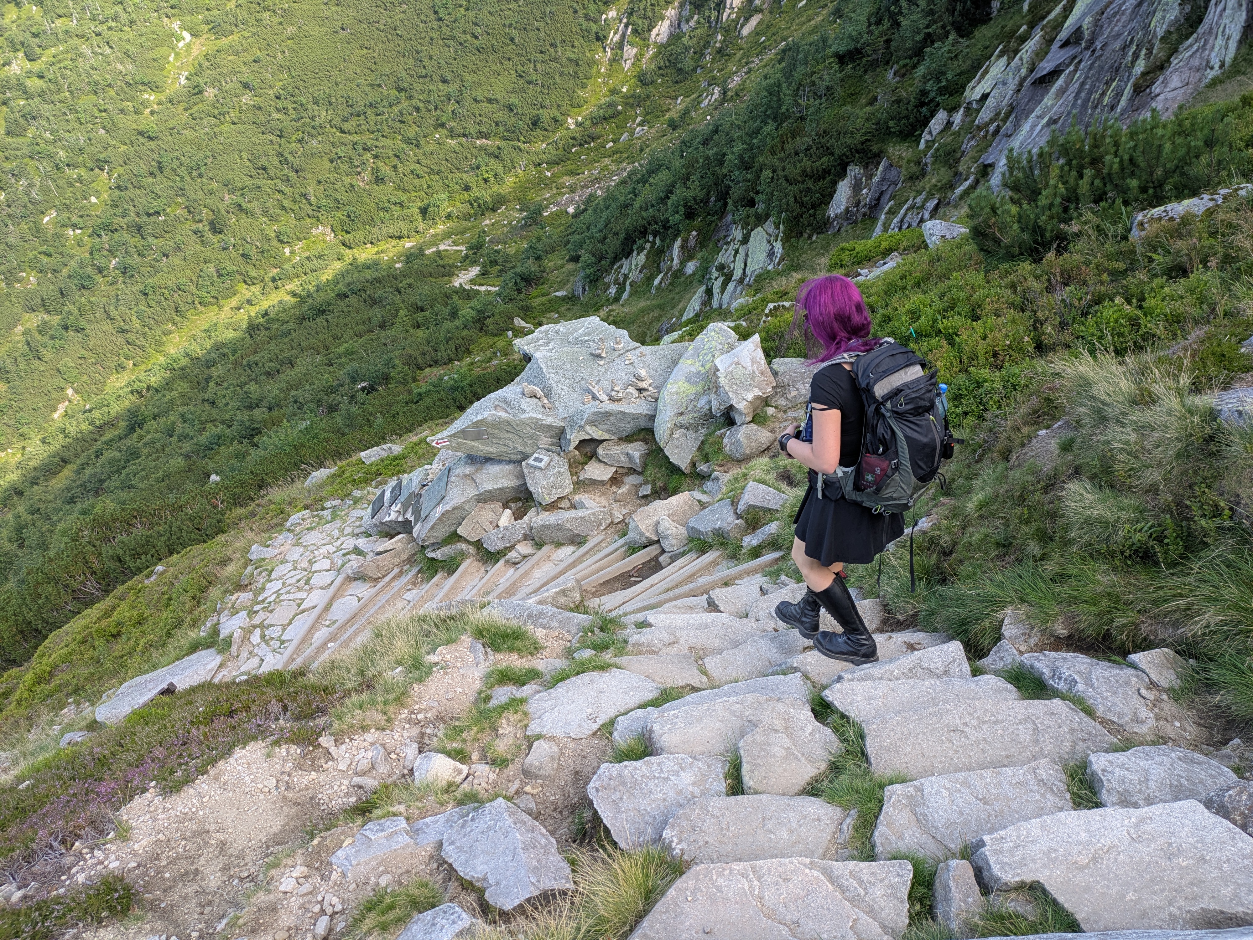
It also features a memorial / symbolic graveyard for all those who passed away on the mountain. You may decide to hum the tune of the Celeste – Resurrections soundtrack at this point.
In any case, once you've made it past the steep part, you're rewarded with a chance to cool off your feet in the Łomniczka stream, and easy walking for the remaining hour or so to Karpacz.
As usual, our trip ended at around 19:00, and more photos are available at lib.finalrewind.org/Słonecznik 2025.
Krkonoše day 1: Sněžka (snow top) to Soví sedlo (owl pass)
This is the first of four posts about our 2025 vacation in the Giant Mountains (Krkonoše / Karkonosze), see Vacation in the Giant Mountaints for an introduction.
On our first full day, we decided to start with the most obvious target: Sněžka (snow top / Schneekoppe), the highest summit of the Giant Mountains (and also of the Sudetes mountain range and of the Czech Republic).
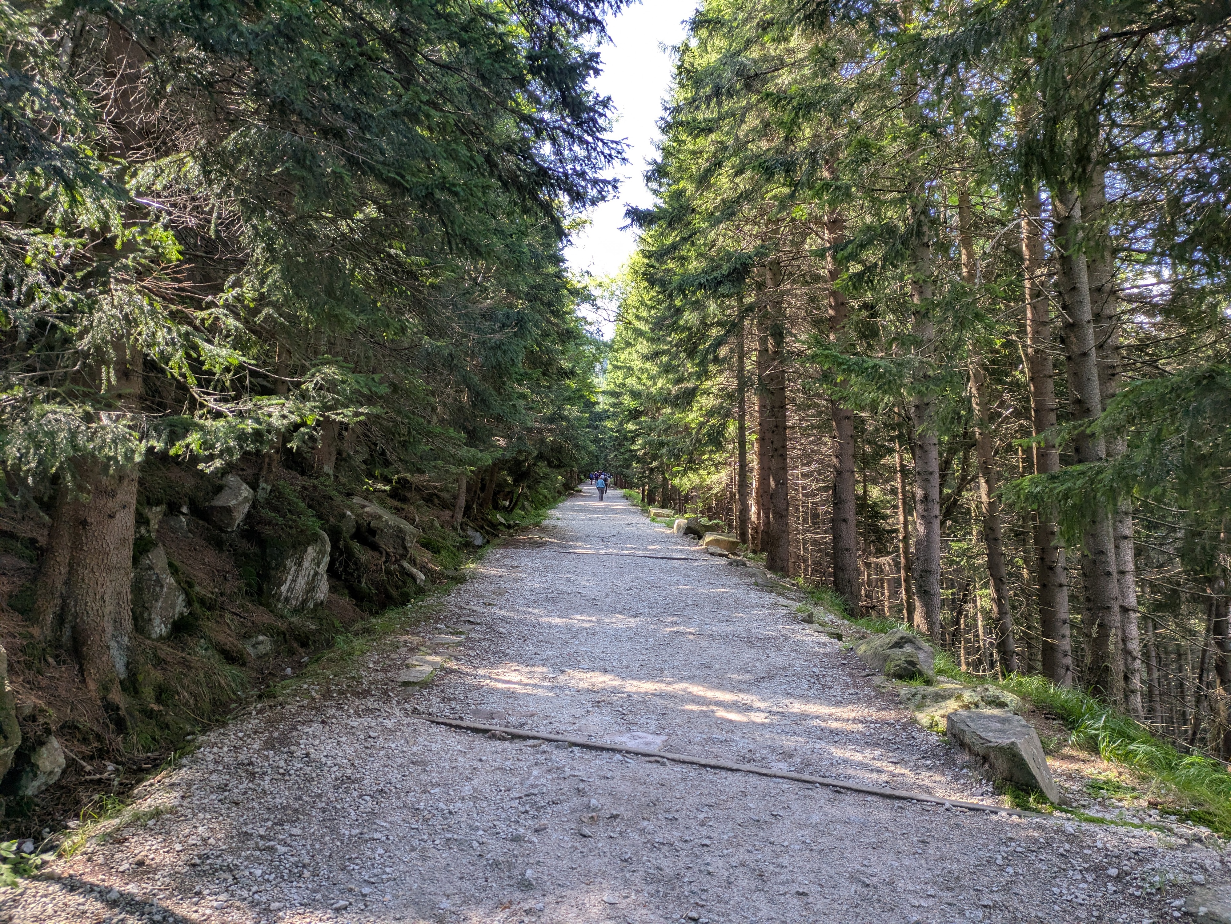
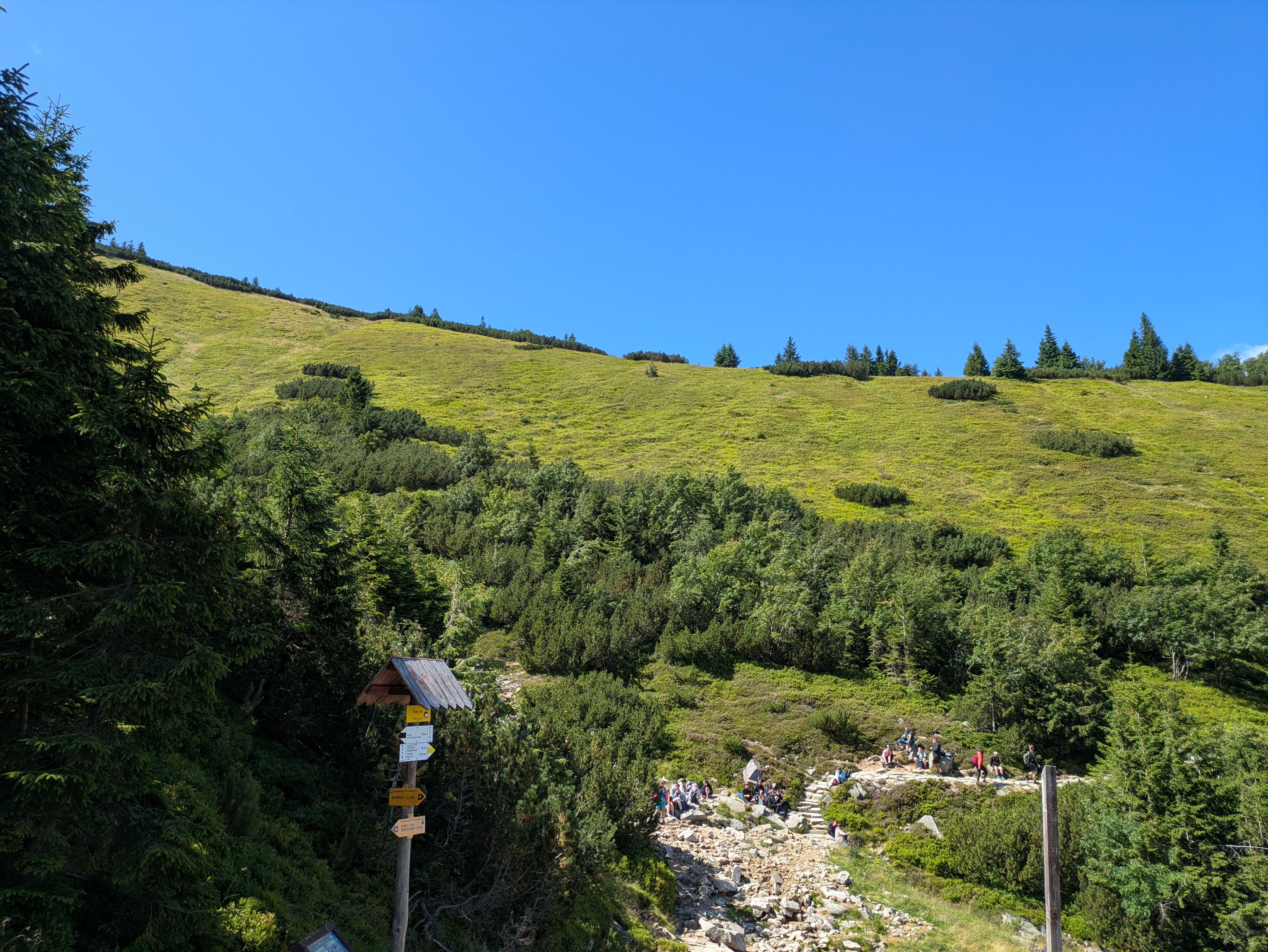
Starting near Karpacz train station (600m) at about 09:00, we took the Śląska Droga path from the outskirts of Karpacz (800m) to Biały Jar (1225m), which we reached at about 11:00. It's steep, but easy terrain, and seems to be the main tourist trail from Karpacz up to Sněžka: it wasn't exactly packed, but definitely crowded. As neither of us hike up mountains every day, we made frequent breaks along the way – there aren't too many (free) seats or benches, but plenty of stones that can serve as seats when needed.
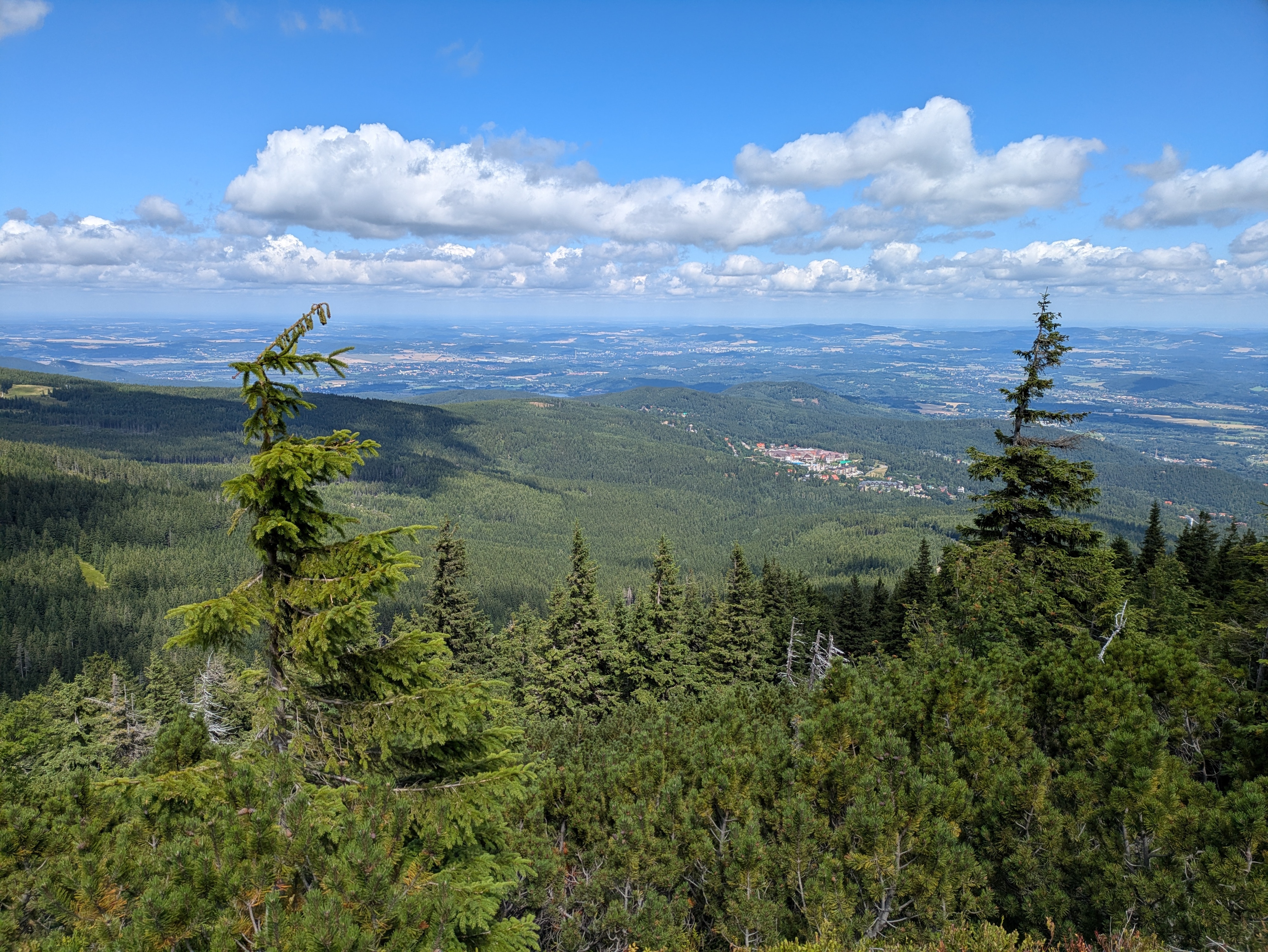
Up next is a relatively even segment via the Zbyszek's upper aerial way station and Dom Śląski (Silesian house); we got there at about 12:15. The path already offers some nice views down into the Polish lowlands and towards Sněžka, and also seems to be quite popular. It's close to the timber line, and you can already see the vegetation getting smaller and more compact.


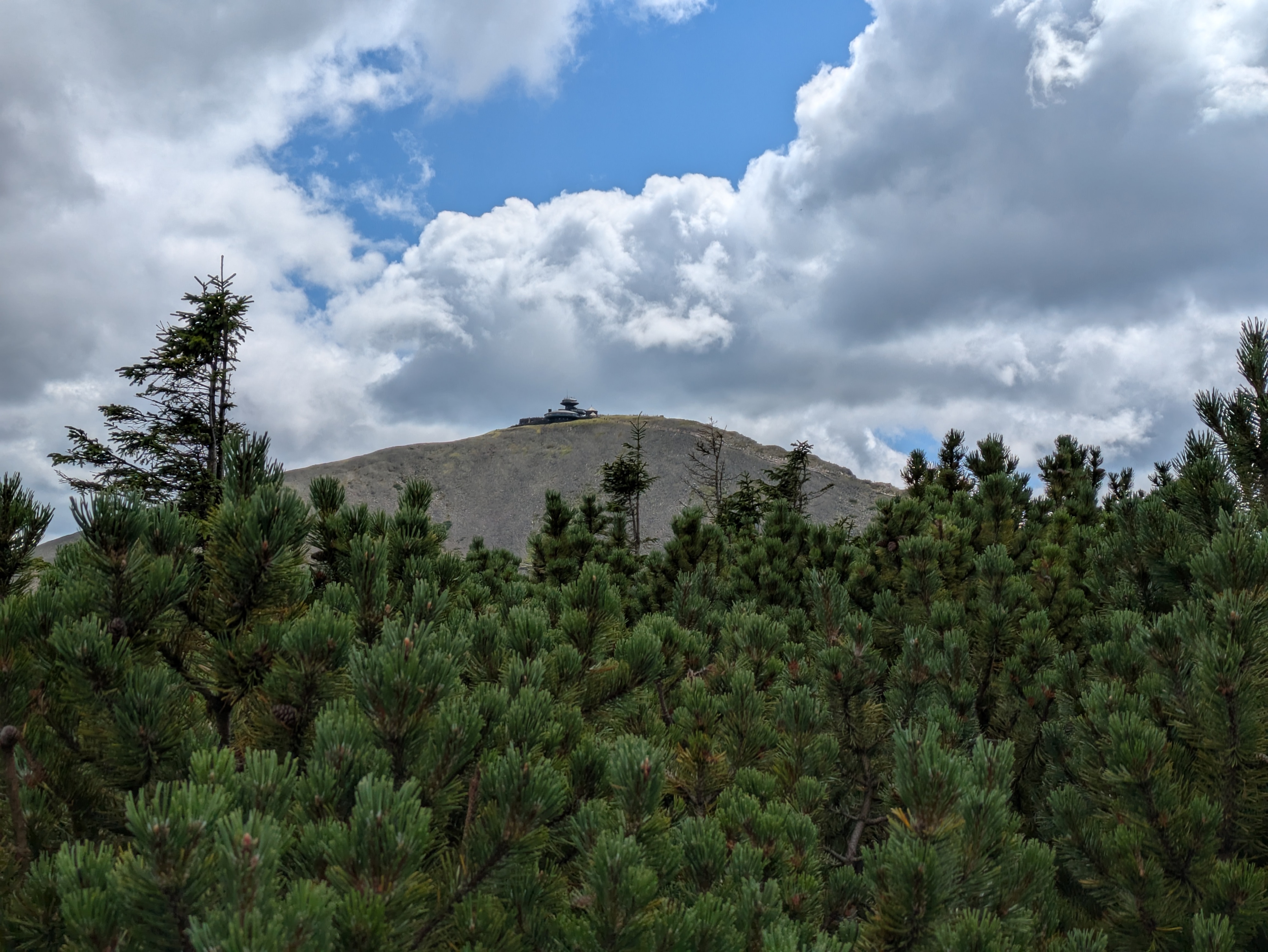
Finally, we took a segment of Droga Przyjaźni Polsko-Czeskiej (the Polish-Czech friendship trail) for the final serpentine climb up Sněžka (1603m). This is a pretty steep and stony one-way path; alternatively, Droga Jubileuszowa (Jubilee road) offers a less steep way up through better terrain. Droga Przyjaźni Polsko-Czeskiej definitely has the better views – you get to look into an unnamed and unpopulated Czech valley and can also see the next range of the Giant Mountains and the Czech lowlands behind it, as well as a plateau of the Giant Mountains to the west.


Sněžka itself was pretty crowded, but a good spot for radio experiments, so we stayed there from about 13:00 to 13:50. The views are nice, but the paths around it are more interesting. The Sněžka peak sits comfortably above the timber line, so there is hardly anything growing there at all.


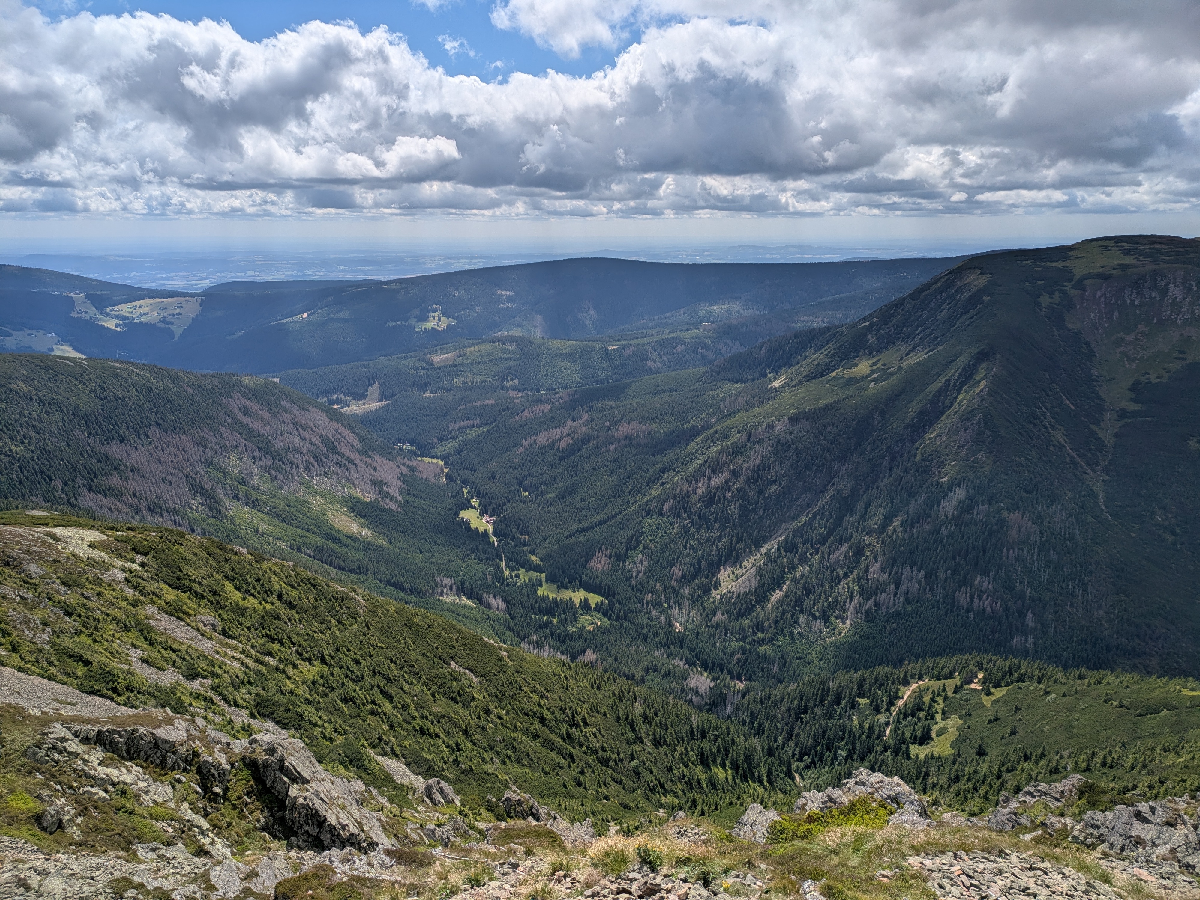
We quickly scrapped our original plan of returning via Śląska Droga, and instead chose to follow Droga Przyjaźni Polsko-Czeskiej to the east until we'd find the next path down to Karpacz at Soví sedlo / Sowia Przełęcz (owl pass / Eulenpass). This turned out to be an excellent idea – the path was far less busy, and really drove home just how much a few dozen metres of ascent or descent affect the height of the vegetation next to the path. As the trail largely follows the Czech–Polish border, you'll frequently pass border stones.
Also, the views back to Sněžka and to either side are, unsurprisingly, very good.


We reached Soví sedlo / Sowia Przełęcz (owl pass / Eulenpass) at about 15:20. The way back to Karpacz took us through a valley next to the Płomnica (Plagnitz) stream and was easily as steep as the ascent towards Biały Jar and Sněžka, just with a bit more serpentine segments and less even surfaces. There's lots of fruit growing in the upper parts of the path, and plenty of water (including on the trail itself) further down.
We returned to our room near Karpacz train station at about 18:30. More photos are available at lib.finalrewind.org/Sněžka 2025.
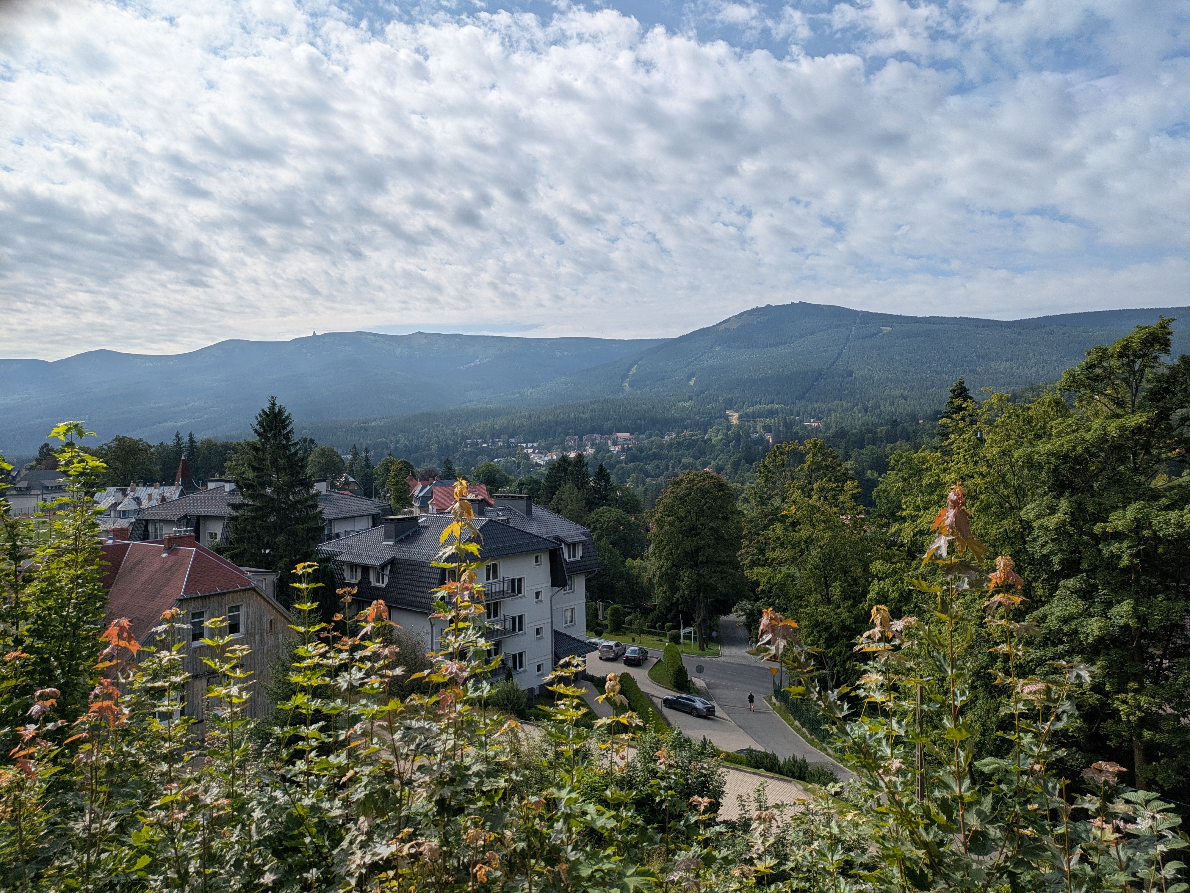
In early August 2025, dm2lct and I spent a few days in the Giant Mountains (Krkonoše / Karkonosze) at the Czech/Polish border. Specifically, we booked a room in Karpacz, a town at the foot of the Sněžka, which happens to be the highest summit of the Giant Mountains (and also of the Sudetes mountain range and of the Czech Republic).
The Giant Mountains are absolutely worth a visit – we've been there for four days and I feel like we've seen quite a lot, but certainly not all of the diverse landscapes and views they have to offer. Just note that, unless you want to take one of the few lifts scattered throughout the mountain range, you'll have to climb 700 to 1,000 metres each day depending on where you are staying and where you are going.
I'll write separate blog post for each of the four days (i.e., for each of the four summits / parts of the mountain range that we visited during our stay). This one just serves as a documentation of arrival, departure, and some notes on Karpacz and the Karkonosze National Park (Karkonoski Park Narodowy / KPN) in general.
Arrival
There is a connection from Dresden to Karpacz every other hour, and the entire trip takes about four hours when everything goes well. In our case, we started with a delayed bus to Bautzen, thus leading to a far longer layover in Görlitz than anticipated. Görlitz is absolutely worth a visit though, so no harm done.
- Trilex RE1 Bautzen (11:16) → Görlitz (11:50)
- KD D19 Görlitz (13:39) → Jelenia Góra (15:15)
- KD D62 Jelenia Góra (15:32) → Karpacz (15:56)
Karpacz
Karpacz looks like a pretty typical Polish tourist town. It offers plenty of hotels, pensions, and more simplistic renting options, and also plenty of restaurants and kitsch. There are two supermarkets close to the train station, and a few more scattered throughout the remainder of the city. Note that most restaurants close between 20:00 and 22:00, so you should not wait too long in case you still want to have a warm meal after a day of hiking up and down the mountains.
On the language side, learning some Polish beforehand is a good idea. In our case, some remnants of school Polish and a dictionary on the smartphone were sufficient most of the time. At least a few people also speak at least a little bit of English; we didn't try German.
Karkonoski Park Narodowy (KPN)
The entire Polish side of the giant mountains is covered by a national park, entry to which costs 8 to 11 Złoty (about 2 €) per day and person, depending on whether you buy a single-, two-, or three-day pass. Especially on the popular tourist trails, you will find staff selling tickets at one of the entrances to the park – of course, you can pay by card, even at 1,000m above sea level. You also have the option of buying day passes online and then presenting those on your smartphone or as a print-out. The trails inside the park are mostly well-kept and seem like the upkeep isn't that cheap, so overall, I'd say the fee is justified.
We did not encounter any ticket checks inside the park or on the way out, and there were also no ticket checks (or sales) on the ridges and peaks, which frequently criss-cross between Poland and the Czech Republic. So, if you're entering the Giant Mountains from the Czech side, you probably don't need a ticket even if you enter KPN area every now and then.
Departure
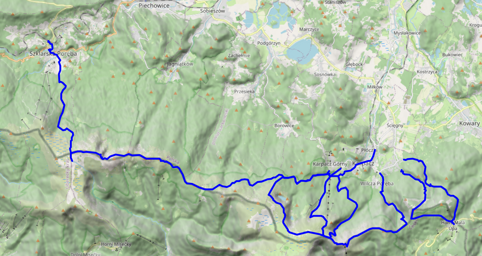
Due to several Nazi demos in Bautzen, we were not too keen on taking Trilex RE1 on the way back. As the line to Tanvald / Liberec was closed as well, we instead opted for the long way round: Karpacz → Sędzisław → Trutnov → Praha → Děčin → Bad Schandau → Dresden. This took the better part of the day and was absolutely worth it.
- KD D62 Karpacz (06:52) → Jelenia Góra (07:15)
- KD D6 Jelenia Góra (07:22) → Sędzisław (07:49)
- KD D26 / Os 25425 Sędzisław (07:58) → Trutnov střed (08:45)
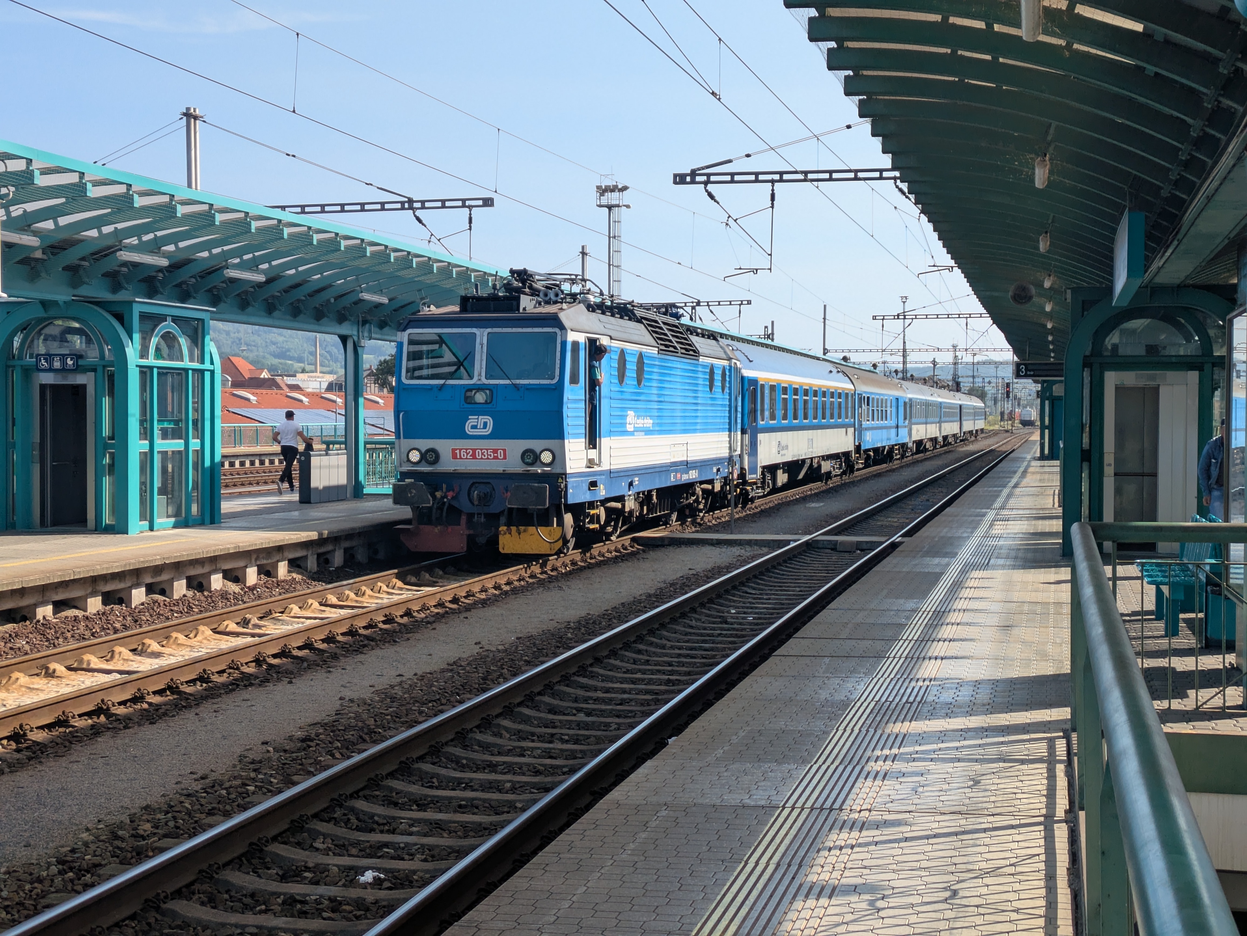
- ČD R10 “Krkonoše” Trutnov střed (08:47) → Praha hlavní nádraží (11:42)
- ČD R20 “Labe” Praha hlavní nádraží (14:45) → Děčin (16:33)
- RB U28 Děčin (16:41) → Bad Schandau (17:11)
- S1 Bad Schandau (17:14) → Dresden Hbf (17:58)
The whole endeavour cost us about 60 € (about 30€ per person):
- Karpacz → Jelenia Góra: – (vending machine was broken and the conductor didn't know how to sell cross-country tickets, so we got to travel for free)
- Jelenia Góra → Královec: 40 PLN (about 10€)
- Královec → Trutnov: 102 CZK (4.20 €)
- Trutnov → Děčin: 999 CZK (41.13 €)
- Děčin → Schöna: 80 CZK (about 4 €)
- Schöna → Dresden: Deutschlandticket
Also, I'd like to note that the official České Dráhy app (Můj vlak) is easily the best official railway app I've ever used. It has detailed and up-to-date information about trains, free/reserved seats, delays / disruptions / construction sites, and anything else you need. Also, despite booking a conventional day ticket for two adults that was not even bound to specific trains, we were able to reserve seats on R10 and R20 free of charge. Rail travel in Poland doesn't even come close.
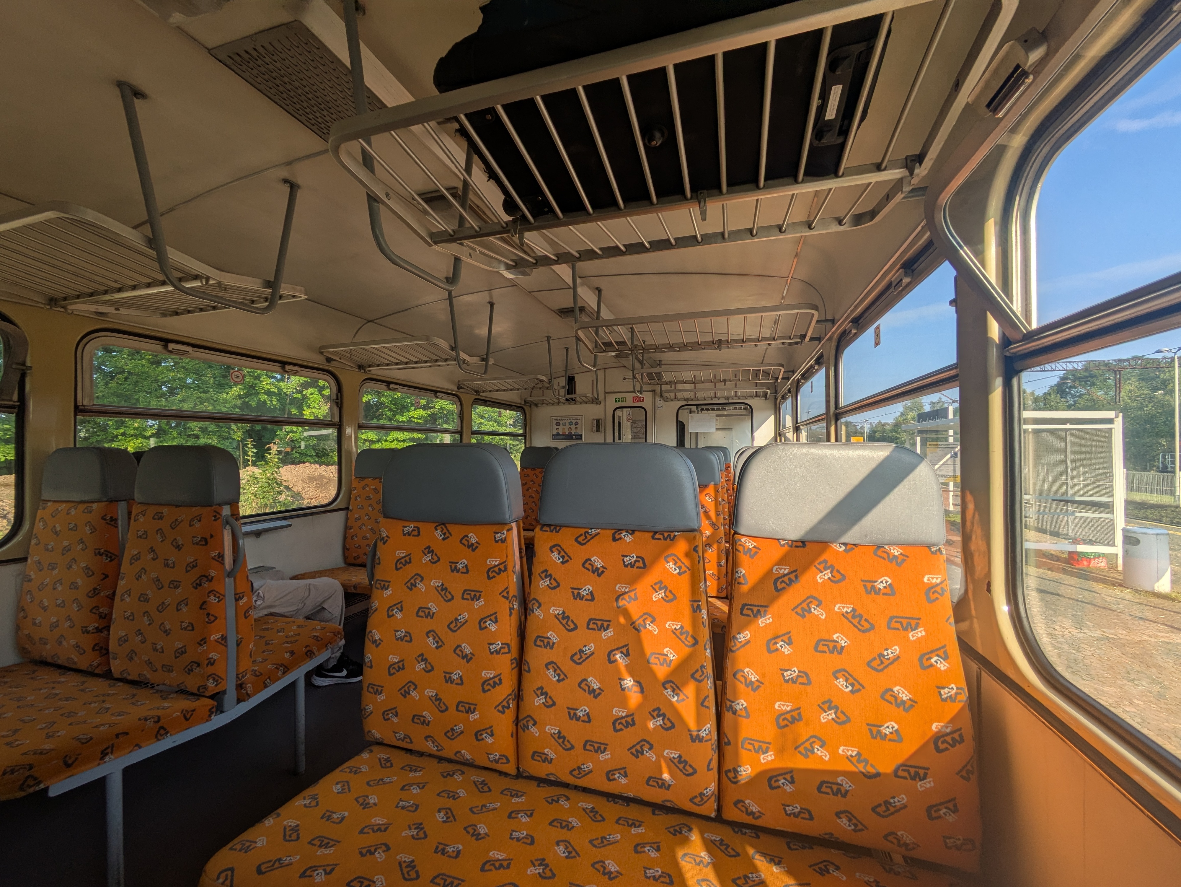
Sędzisław → Trutnov
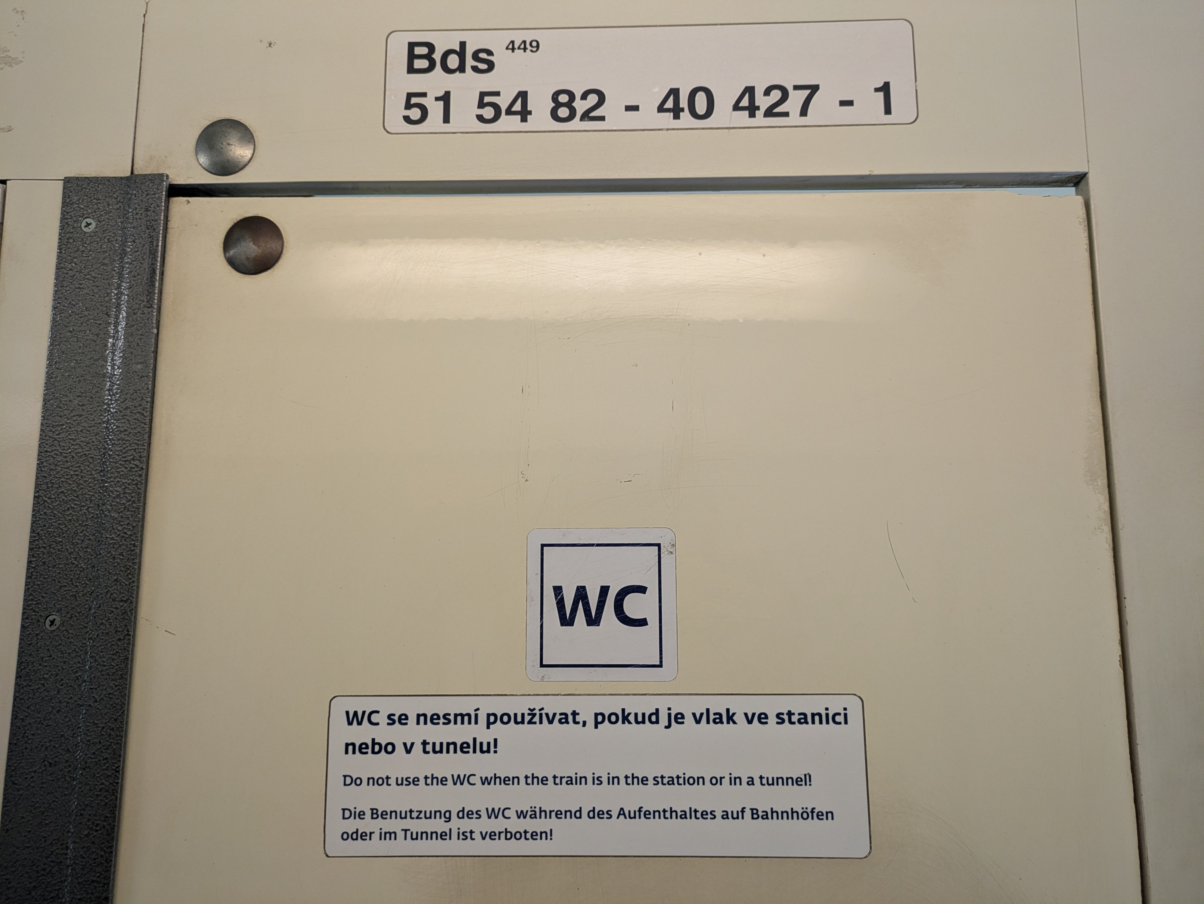
We did not look up the rolling stock beforehand, and were positively surprised when we encountered a ČSD M 152.0 (“Brotbüchse”) on the cross-border line from Poland to the Czech Republic. It's a single-carriage Diesel train, using a conventional omnibus motor, and was pretty empty – at least on the early Sunday morning at which we were travelling. It's not exactly modern or fast, but does its job and got us to Trutnov almost in time. From a nostalgia point of view, this was quite the jackpot.
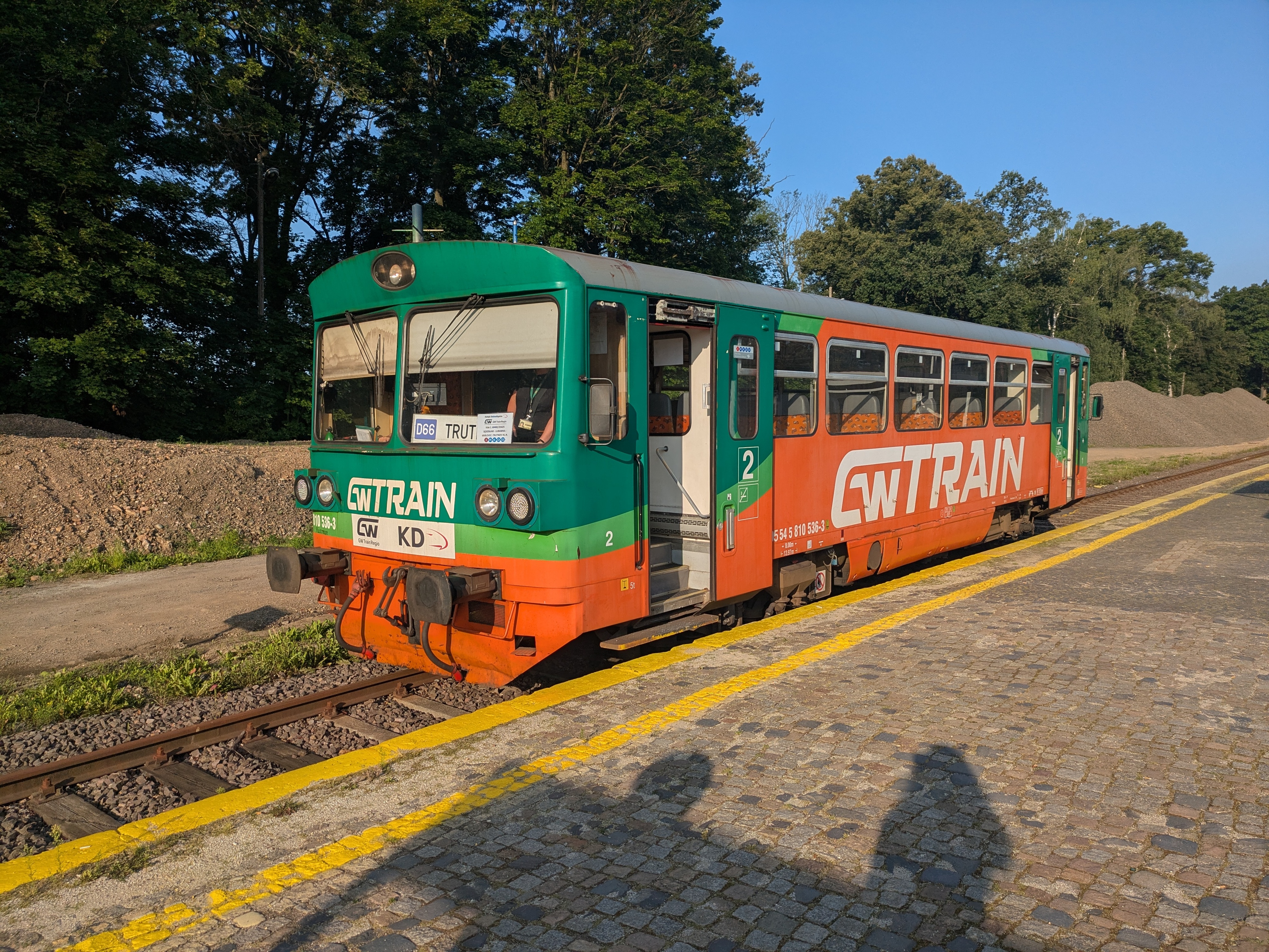
Luckily, the layover in Trutnov střed happens before a single-track segment, with the train from Sędzisław coming from the segment that the R10 to Praha has to pass after departure. hence, although our train from Poland had two minutes of delay, the R10 was waiting for us on the same platform and we could still board it. I have no idea whether this connection always works that well.
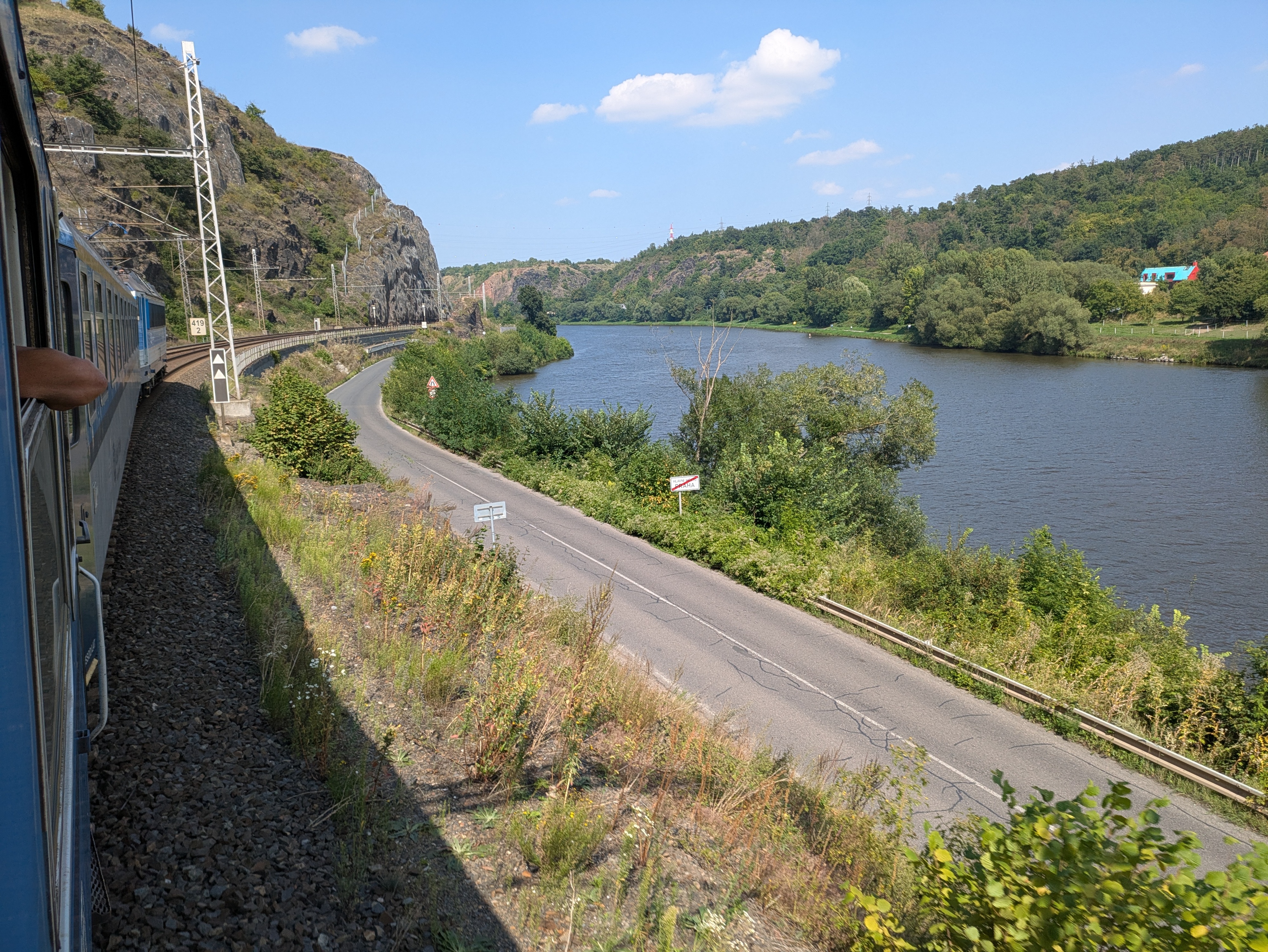
Praha → Děčin
Our ticket would have allowed us to take a EuroCity, but dm2lct specifically suggested the R10 line. As of 2025, its rolling stock still includes a luggage wagon that contians four 8-person compartments – and features windows that you can actually open. You hardly ever see that anymore these days, so taking this train on the way back also was quite a treat. The noise at an open window can be deafening at times, though – both the wheels and the brakes are anything but quiet, especially when walls or rocks next to the tracks reflect their noise back towards the train.
Enabling Filesystem Quotas on Debian
Because I keep forgetting how I do it, here's how to enable filesystem quotas on a reasonably recent Debian server.
For simplicity, let's say the mountpoint is /home and the device /dev/storage/home.
sudo apt install quota
- Add
usrquotaas a mount option to the/etc/fstabfor/home
sudo systemctl daemon-reload
sudo umount /home
sudo tune2fs -O quota /dev/storage/home
sudo mount /home
For usrquota alone, a remount should be sufficient, but tune2fs needs to run offline in this case.
Now, all that's left is setting quotas.
This only needs to be run once for each new account, preferable automatically as part of some kind of account management system.
setquota -u account block-soft block-hard inode-soft inode-hard /home
You can check quota settings and usage with repquota -as.
Installing Debian on a ThinkPad T14s Gen 6 with Intel CPU
When setting up my new work laptop (replacing the more than eight years old X270 that I used before), I found that the freshly installed Debian unstable was unable to produce any kind of graphics output. X11 complained about not finding any screens, and the text console also broke as soon as the kernel tried configuring it. Long story short: Turns out that Linux 6.12, as shipped with Debian unstable, is simply too old for Intel Arc 130V/140V graphics and/or Intel Lunar Lake / Core 258V CPUs. With Linux 6.14, everything works right out of the box.
Luckily, you can just install Ubuntu kernels on Debian. So, solving this issue was as simple as issuing the following commands:
wget \
  https://kernel.ubuntu.com/mainline/v6.14/amd64/linux-headers-6.14.0-061400-generic_6.14.0-061400.202503241442_amd64.deb \
  https://kernel.ubuntu.com/mainline/v6.14/amd64/linux-headers-6.14.0-061400_6.14.0-061400.202503241442_all.deb \
  https://kernel.ubuntu.com/mainline/v6.14/amd64/linux-image-unsigned-6.14.0-061400-generic_6.14.0-061400.202503241442_amd64.deb \
  https://kernel.ubuntu.com/mainline/v6.14/amd64/linux-modules-6.14.0-061400-generic_6.14.0-061400.202503241442_amd64.deb
sudo apt install \
  ./linux-headers-6.14.0-061400_6.14.0-061400.202503241442_all.deb \
  ./linux-headers-6.14.0-061400-generic_6.14.0-061400.202503241442_amd64.deb \
  ./linux-modules-6.14.0-061400-generic_6.14.0-061400.202503241442_amd64.deb \
  ./linux-image-unsigned-6.14.0-061400-generic_6.14.0-061400.202503241442_amd64.deb
The new kernel version is automatically picked up by GRUB, so one reboot later everything worked as intended.
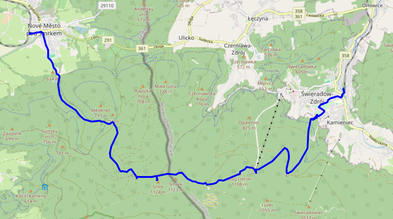
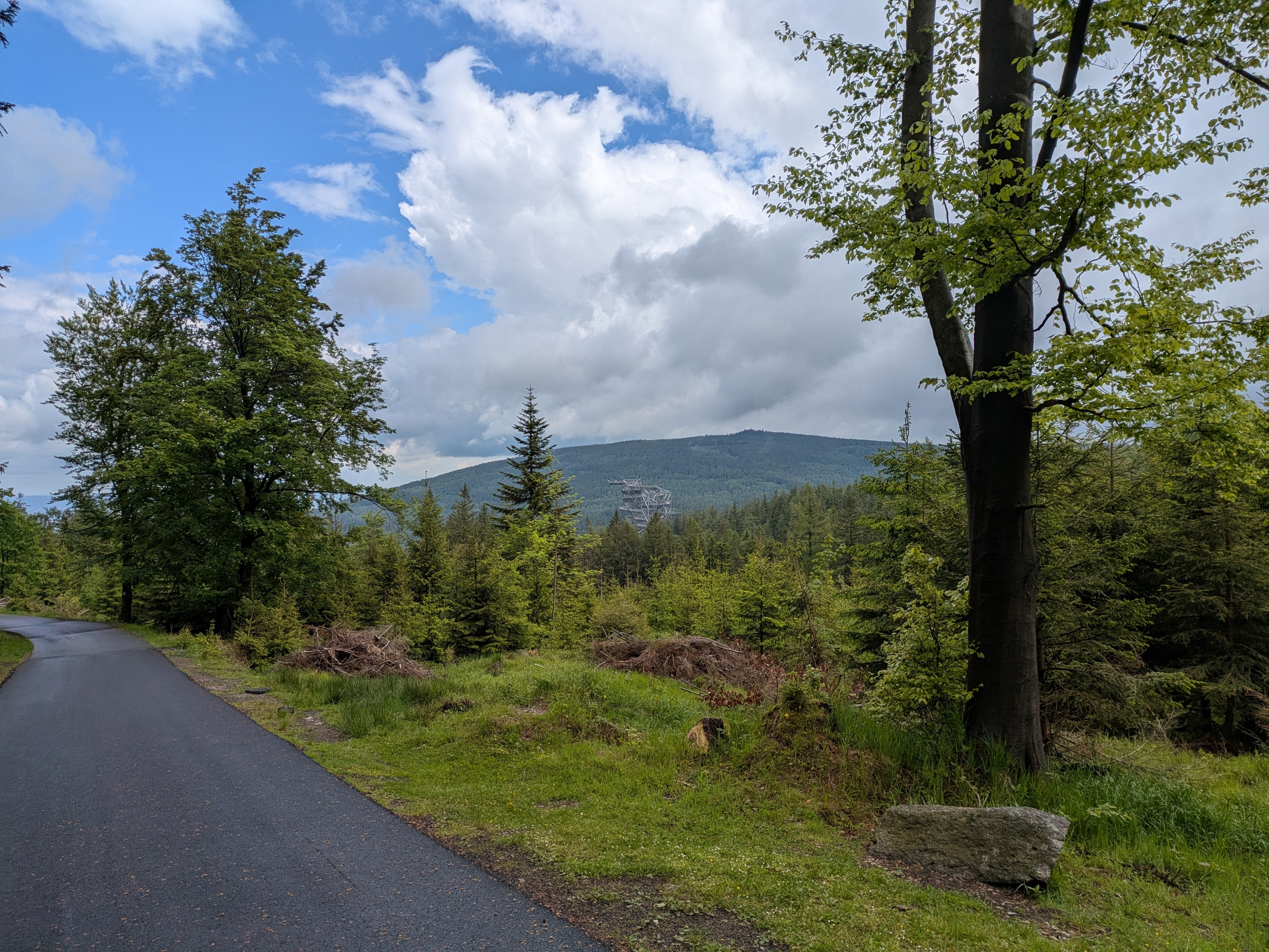
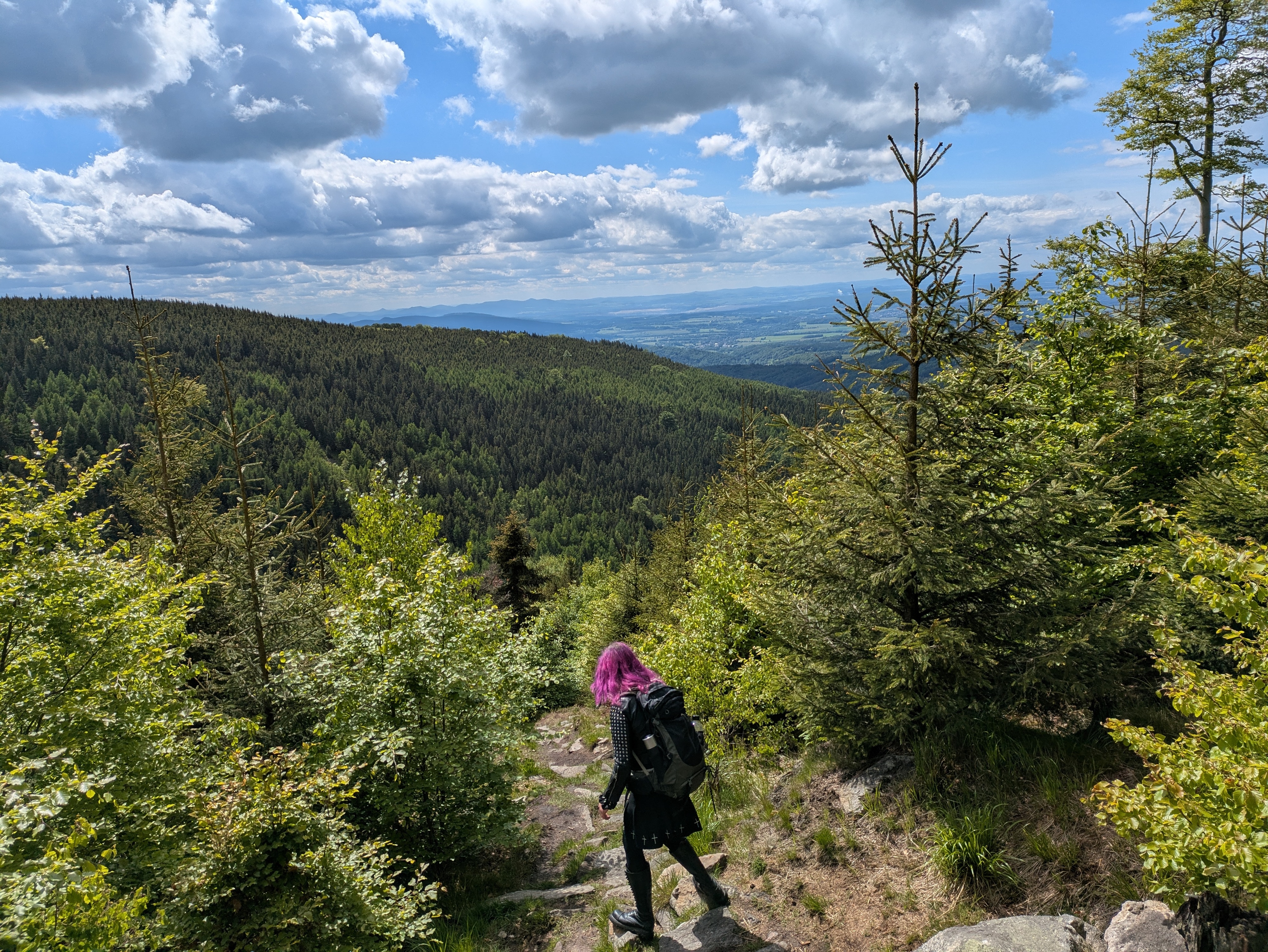
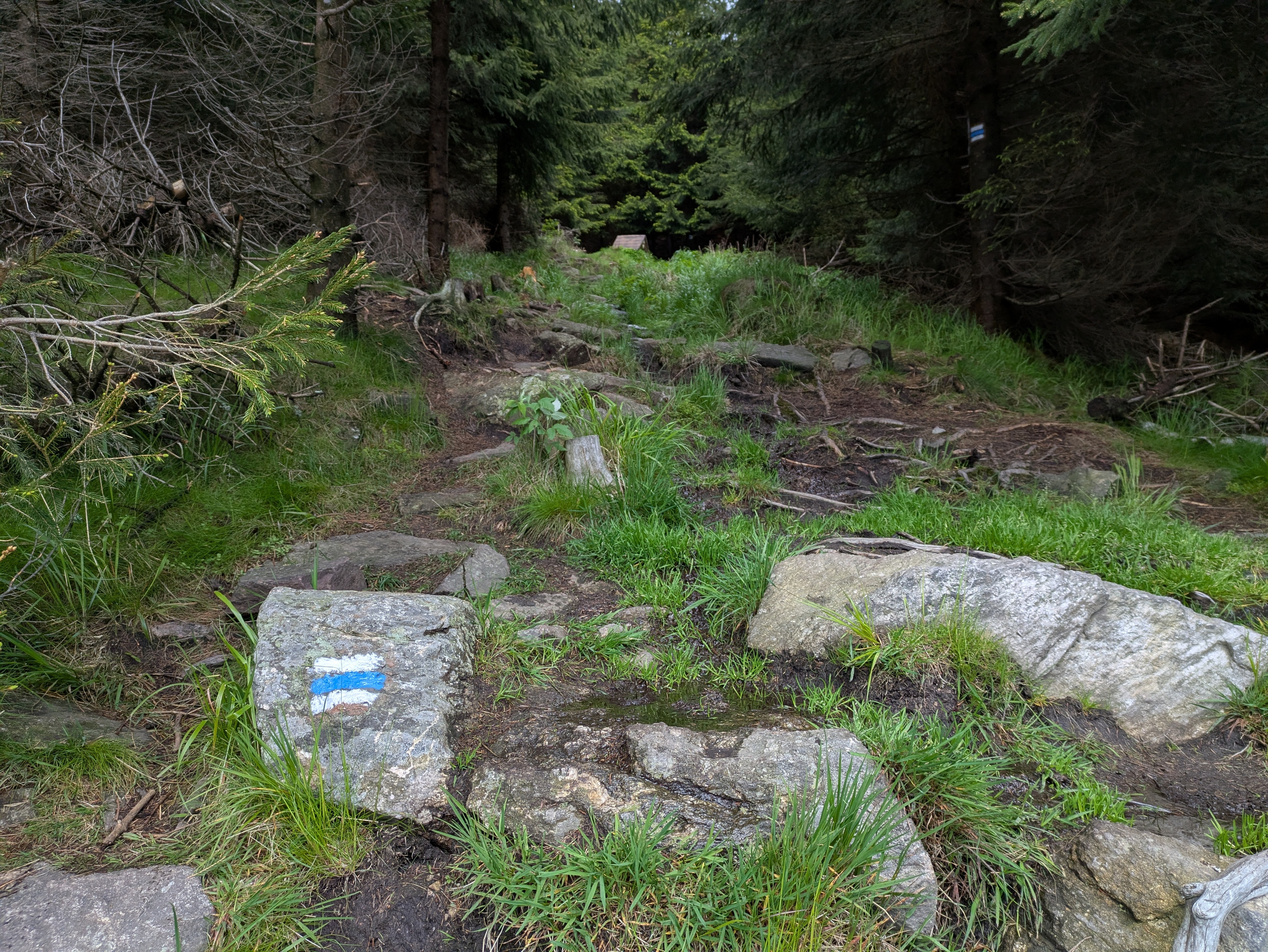
In late May 2025, dm2lct and I hiked across the Jizera mountains (CZ: Góry Izerskie / PL: Jizerské hory / DE: Isergebirge), right at the Czech – Polish border. It's a very nice hike with some stunning views, and doable as a single-day trip from and back to Dresden – even with rail replacement services here and there. Just note that you might want to wear water-tight boots – at least when we were up there, the majority of hiking trails on the summit were actually water streams.
See jizera-mountains.gpx for the approximate route we took. Note that I traced it after the fact, as we did not use GPS logs on our hike.

Arrival
We decided to start our climb from Świeradów-Zdrój (DE: Bad Flinsberg) on the Polish side of the mountains. We did have to get up at a slightly ungodly hour, but that was definitely worth it.
- TL RB60 Dresden Hbf (06:53) → Görlitz Hbf (08:33) – Deutschlandticket
As the direct connection to Zgorzelec was closed, apparently due to issues related to the German/Polish language level of the train drivers, the route to Świeradów-Zdrój included a nice little 50-minute detour through the twin towns of Görlitz and Zgorzelec. I think I'll come back for a proper visit to Görlitz old town on a later day. It even has a small tram network! Zgorzelec train station is quite cozy as well, featuring a small café right next to the waiting room.
- KD 69874 Zgorzelec (09:44) → Świeradów-Zdrój (10:55) – 18.75 PLN (4.45 €) each
The tracks in Poland had very noticeable rail joints – and a tight curve in Lubań actually mannaged to topple our water bottle. Apart from that, it's a pretty standard Diesel train connection, ending at the single-platform terminus in Świeradów-Zdrój.
Going Up
Świeradów-Zdrój sits about 500 metres above sea level; the Jizera and Smrk peaks clock in at 1,107 and 1,124 metres, respectively. There's a cabin lift to Stóg Izerskie (DE: Heufuder) situated about a kilometre from the train station, seemingly operating year-round, but walking certainly is the more interesting option.
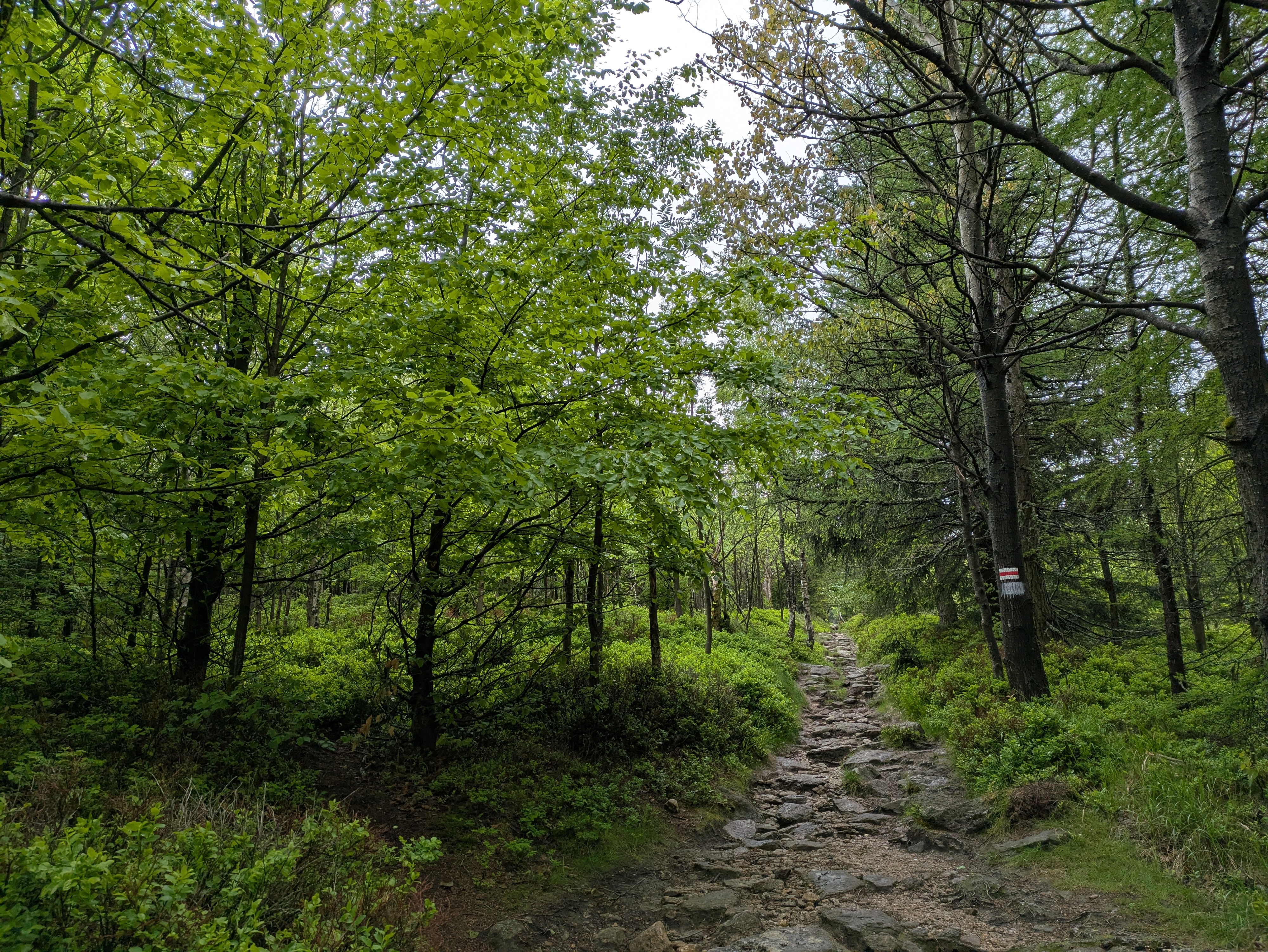
After a few hundred metres through the town itself, you're faced with two options: a (partially serpentine) road, or a more direct (and, thus, steep) gravel-rock-ish path. We chose the latter option, which seems to be marked with a red-on-white stripe.
The path was mostly dry, except for a short segment near the Świeradówka reservoir that basically consisted of walking through a sometimes stony and sometimes just outright muddy water stream. That segment is not mandatory: an asphalt road offers the same way up with a slight (but dry) detour.
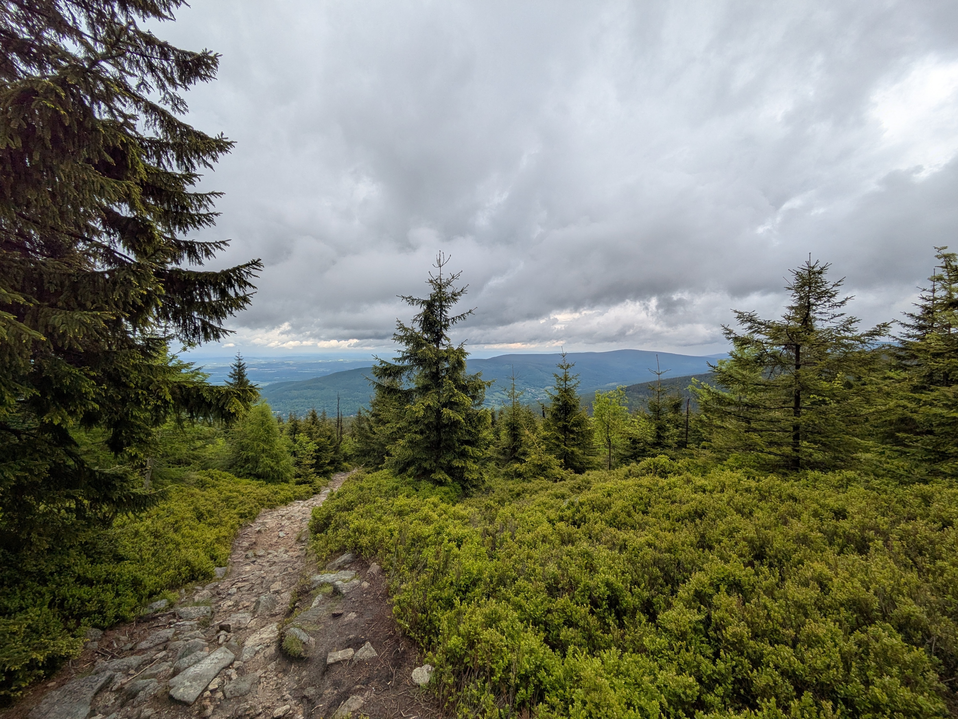
Apart from that, the way up already offers some very nice views into the valley – you just need to turn around and look back every now and then. The views include a wooden obseravtion tower sitting almost in the valley itself. I have no idea why it's there.
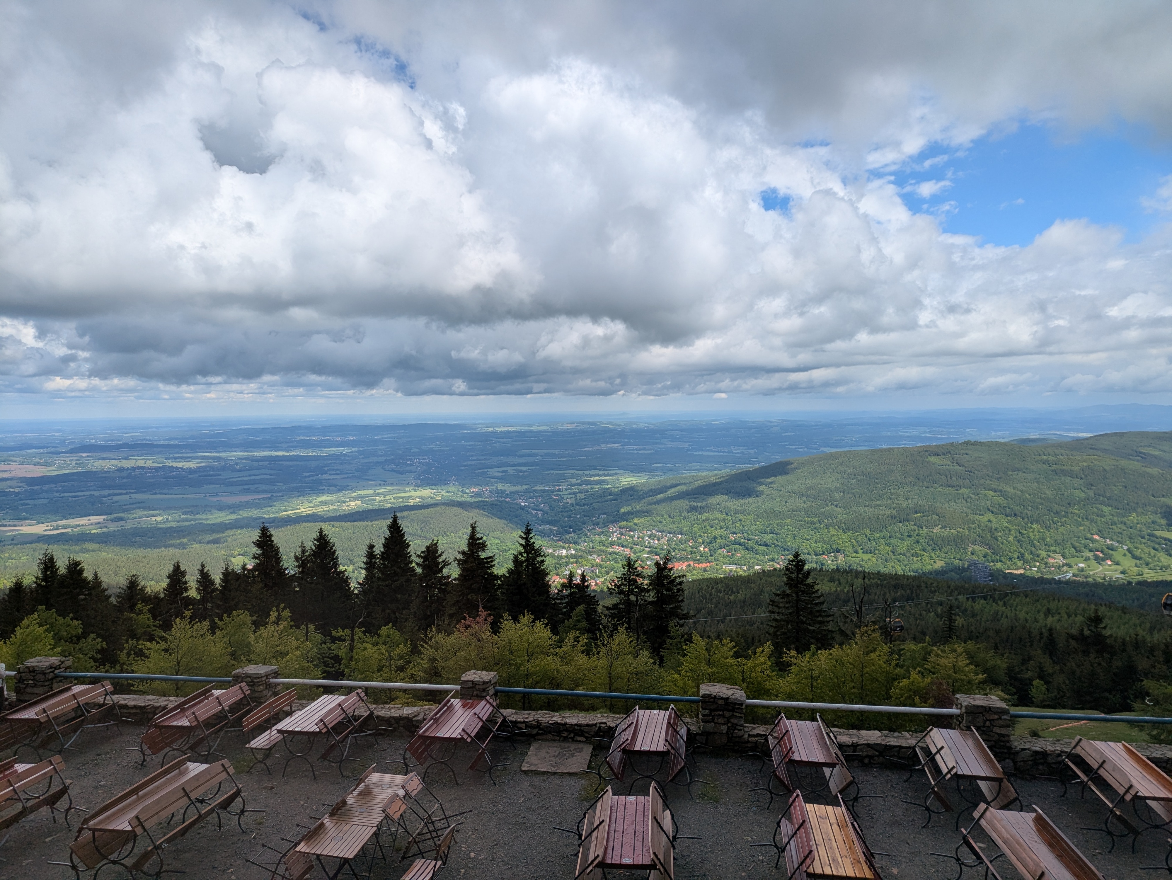
Lunch Break
Once atop Stóg Izerskie (DE: Heufuder), you can stop for lunch at Schronisko na Stogu Izerskim (DE: Heufuderbaude), a hostel/restaurant thingy offering typical Polish food such as Pierogi (a kind of dumplings). Otherwise, you can still go there and enjoy the views from the terrace.
Across the Ridge
Our next stop was Smrk (PL: Smrek / DE: Tafelfichte). It's three metres lower than the highest peak of the Jizera Mountains (namely, Wysoka Kopa / DE: Hinterberg), but features a nice observation deck.
The way to Smrk is comparatively even, but full of water streams that double as trails. It's pretty; just try not to get wet feet. It also features a border crossing from Poland to the Czech republic. In our case, the “welcome to Poland” sign on the way back was missing, but the border stone itself was still present.

View
It's pretty cold and drafty on the observation tower, but the views are absolutely worth it.
Going Down
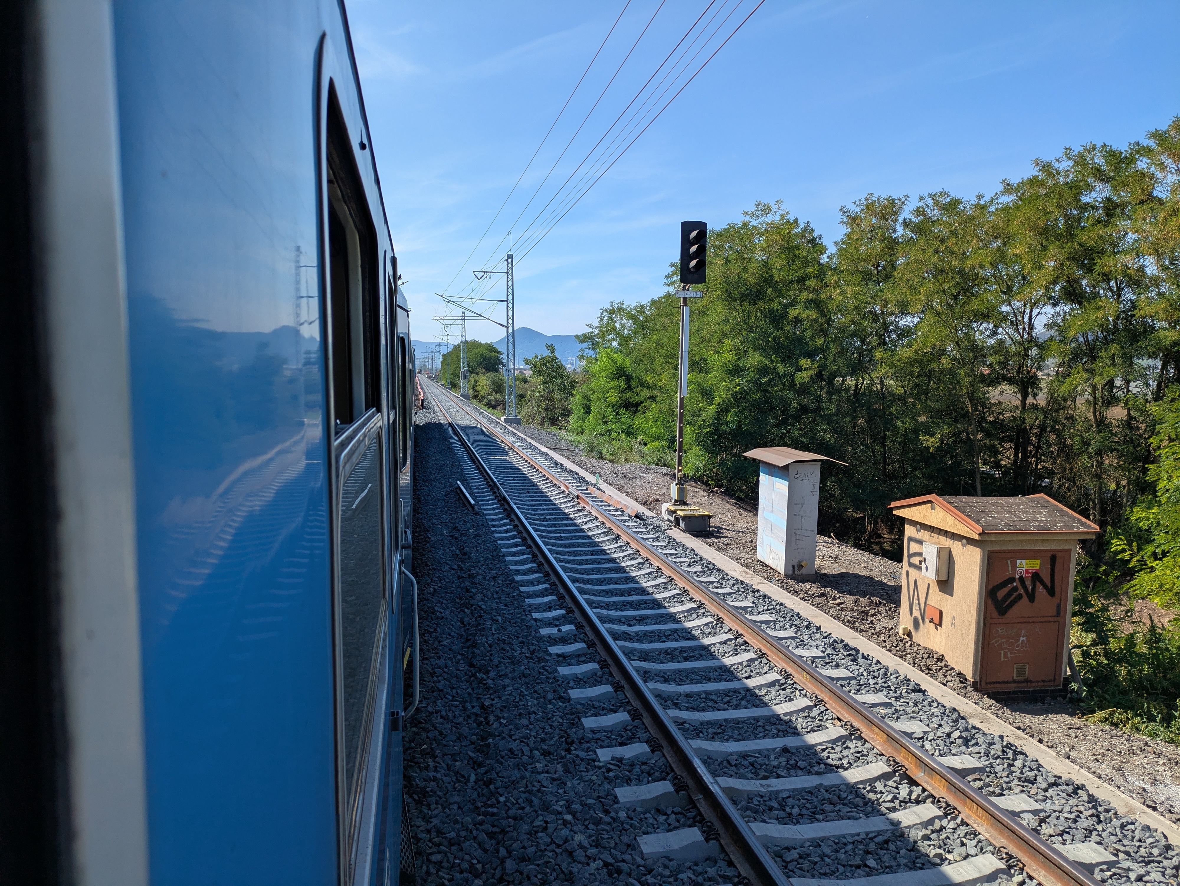
While our original plan was to return to Świeradów-Zdrój, we spontaneously decided that Nové Město pod Smrkem on the Czech side should give for a more interesting trip. It was a bit of a close call – the last train to Liberec departed around 17:00, and there was just a single fallback connection near 19:00 that might still have taken us home in case we missed the one to Liberec. Note that this was regular weekday service.
From the observation tower, you can follow paths marked with a blue-on-white stripe for a reasonably direct, steep, and as often as not watery path down. The views alongside it do not disappoint at all, and even down in the valley there's still quite an angle to the nature around you.

Departure
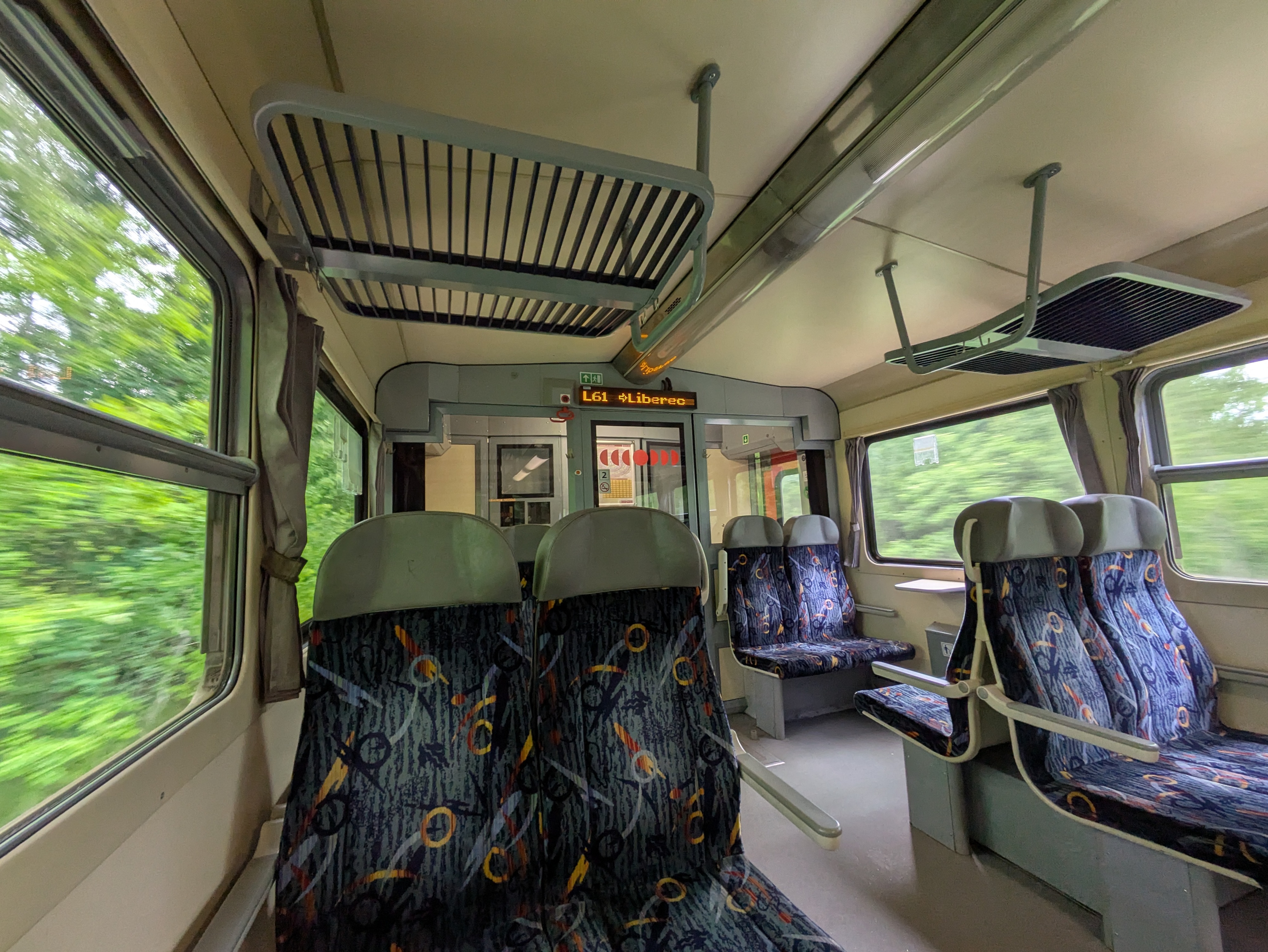
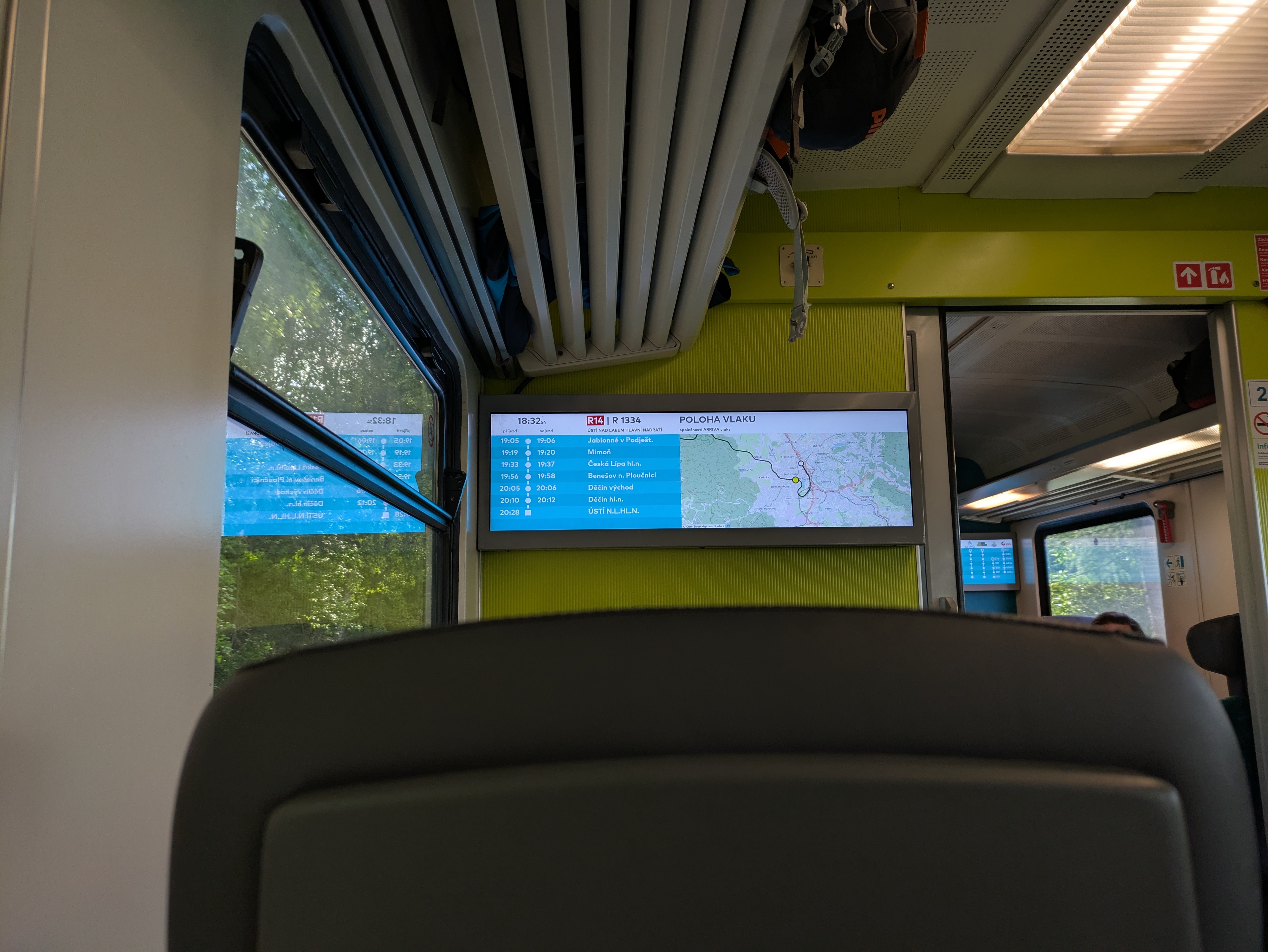
We arrived in Nové Město pod Smrkem at 16:45, 15 minutes before the last train to Liberec departed. Normally, there is a connection from Liberec to Zittau (DE) that would've taken us directly back to Dresden, but as there was only rail replacement bus service available we went with the slightly longer, but at least equally scenic route via Děčín – featuring a nice view towards Ještěd (DE: Jeschken) and its iconic tower. Even on the train, you really notice that the Czech Republic is in more of a mountainside than conventional countryside situation. Also, the ARV train used OpenStreetMap on its passenger information display, which is cool.
- Os 6381 Nové Město pod Smrkem (17:01) → Liberec (17:57) – 70 CZK (2.83 €) each
- ARV 1334 Liberec (18:28) → Děčín hl.n. (20:10) – 196 CZK (7.92 €) each
- RB U28 Děčín hl.n. (20:41) → Bad Schandau (21:09) – 1.80 € or so each
- S1 Bad Schandau (21:44) → Dresden Hbf (22:28) – Deutschlandticket
All pictures from the trip are available on lib.finalrewind.org/Góry Izerskie 2025.
Using cryptsetup / LUKS2 on SSHFS images
Occasionally, I need to open remote LUKS2 images (i.e., files) that I access via SSHFS. This used to work just fine: mount an sshfs, run cryptsetup luksOpen and access the underlying filesystem. However, a recent cryptsetup upgrade introduced (or changed?) its locking mechanism. Now, before opening an image file, it tries to aqcuire a read lock, which will fail with ENOSYS (Function not implemented) on sshfs mountpoints. This, in turn, causes cryptsetup to report "Failed to acquire read lock on device" and "Device ... is not a valid LUKS device.".
There doesn't seem to be a simple way of disabling this (admittedly, in 99% of cases desirable) feature, so for now I'm working around it by just having flock always return success, thanks to the magic of LD_PRELOAD and a flock stub:
#include <sys/file.h>

int flock(int fd, int operation)
{
    return 0;
}
Compile as follows:
> ${CC} -O2 -Wall -fPIC -c -o ignoreflock.o ignoreflock.c
> ${CC} -fPIC -O2 -Wall -shared -Wl,-soname,ignoreflock.so.0 -o ignoreflock.so.0 ignoreflock.o -ldl
And then call LD_PRELOAD=..../ignoreflock.so.0 cryptsetup luksOpen ...
(or sudo env LD_PRELOAD=..../ignoreflock.so.0 cryptsetup luksOpen ...).
ignoreflock provides a handy stub, Makefile and wrapper script for this.
Stop IDs in EFA APIs
EFA-based local transit APIs have two kinds of stop identifiers: numbers such
as 20009289 and codes such as de:05113:9289.
travelynx needs a single type of ID, and this post is
meant mostly for myself to find out which ID is most useful. The numeric one
would of course be ideal, as travelynx already uses numeric IDs in its stations
table.
Numbers
DM_REQUEST: Available as stopID in each departureList entry.
STOPSEQCOORD_REQUEST: Available as parent.properties.stopId in each locationSequence entry.
STOPFINDER_REQUEST: Available as stateless and ref.id.
COORD_REQUEST: missing.
Codes
DM_REQUEST: missing.
STOPSEQCOORD_REQUEST: Available as parent.id in each locationSequence entry.
Outside of Germany, the format changes, e.g. placeID:27006983:1 for a border
marker (not an actual stop) and NL:S:vl for Venlo Bf.
STOPFINDER_REQUEST: Available as ref.gid.
COORD_REQUEST: Available as id and properties.STOP_GLOBAL_ID in each locations entry.
API Input
DM_REQUEST: Accepts stop names, numbers, and codesSTOPSEQCOORD_REQUEST: Accepts stop numbers and codes
Examples
- LinzAG Ebelsberg Bahnhof: 60500470 / at:44:41121
- LinzAG Linz/Donau Hillerstraße: 60500450 / at:44:41171
- NWL Essen Hbf: 20009289 / de:05113:9289
- NWL Münster Hbf: 24041000 / de:05515:41000
- NWL Osnabrück Hbf: 28218059 / de:03404:71612
- VRR Essen Hbf: 20009289 / de:05113:9289
- VRR Nettetal Kaldenkirchen Bf: 20023754 / de:05166:23754
- VRR Venlo Bf: 21009676 / NL:S:vl
Conclusion
Looks like numeric stop IDs are sufficient.
They're missing from the COORD_REQUEST endpoint, but that's not a dealbreaker -- all database-related operations work with DM_REQUEST and STOPSEQCOORD_REQUEST data.
Also, there seems to be no universal mapping between the two types of stop IDs.
PowerCore 5000 Teardown and Repair
I usually carry a PowerCore 5000 powerbank with an attached USB-A to USB-C cable in my purse. In hindsight, always having the cable attached to it (rather than just when using it) is not the best idea, as it exercises quite some leverage forces on the USB port. So, to little surprise, at some point the output port stopped working unless the cable connected to it was pressed into the right direction.
Luckily, the powerbank is quite easy to open up, repair, and re-assemble.
Caution: This powerbank contains a 18.5 Wh LiIon cell. In normal operation, the (dis)charge PCB is in charge of battery management tasks like short circuit protection. Disassembly exposes the raw 26650 LiIon cell, which likely does not contain a built-in protection circuit. Puncturing, shorting, heating, or otherwise mishandling it can lead to fire and/or explosion. Don't disassemble a powerbank unless you know what you are doing. Don't work with soldering irons close to LiIon cells unless you really know what you are doing.
Teardown
The connector side of the power bank features a glued-on plastic cover on top of a screwed-on plastic cover.
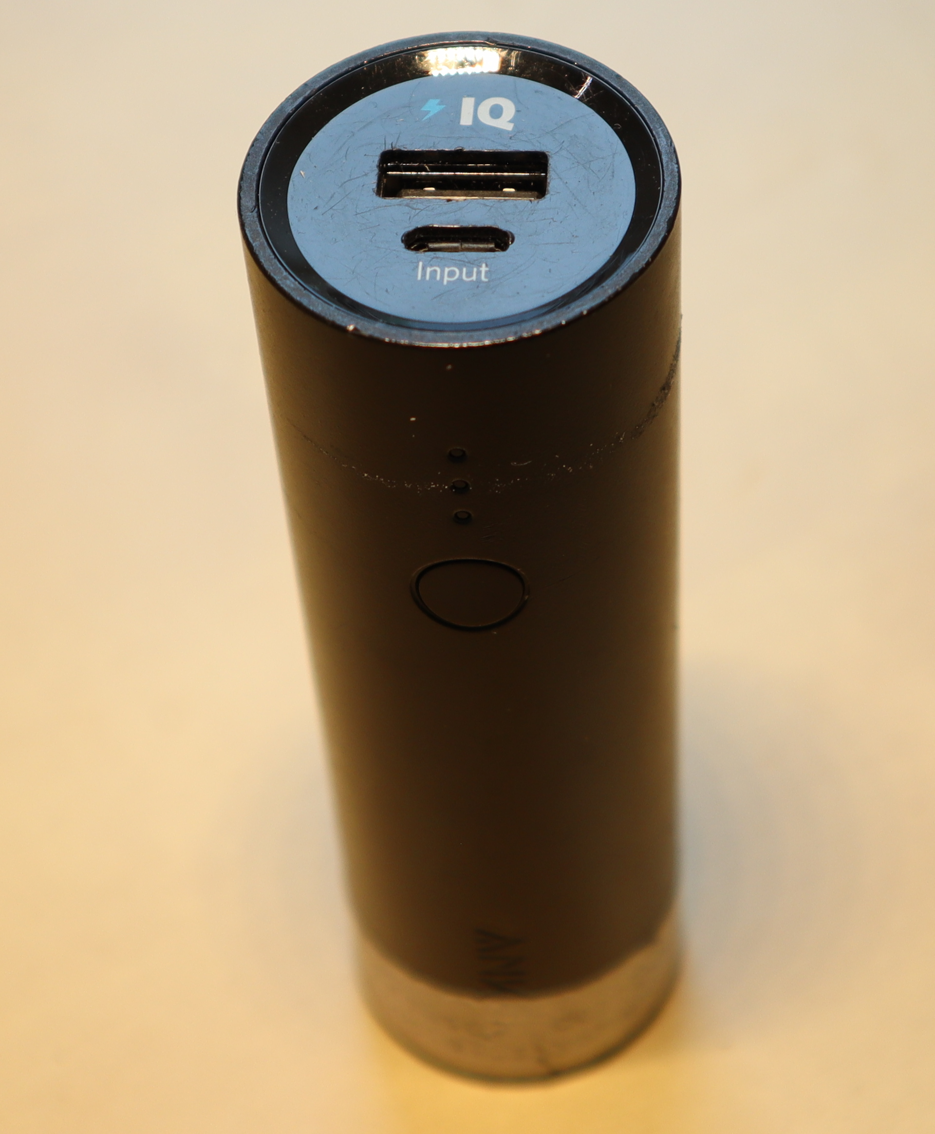
The glued-on cover can be pried open with moderate effort by placing a suitable object between the two plastic covers, revealing the screwed-on second plastic cover.

With the powerbank placed on a table (not held in your hands), you can now take a PH00 screwdriver to release the three screws that hold it in place. Once that is done, simply lift the case up, revealing the actual circuitry (LiIon cell and PCB). If you were holding the powerbank in your hands while removing the screws, the circuitry likely fell out instead.

The innards are quite simple: A single 26650 LiIon cell; a single PCB; and a two-part plastic assembly featuring a button and LED diffusors.


Repair
In my case, the culprit was a loose solder connection between the USB-A output port and the PCB. Nudging the capacitor out of the way and carefully applying some additional solder to its GND and VCC pins solved the issue. Just be wary of the fact that you're operating a soldering iron next to a LiIon cell that does not like triple-digit temperatures…
Re-Assembly
- Slide the button assembly and diffusor back into the case until it locks into place.
- Slide the LiIon cell and PCB assembly back into the case.
- Place the powerbank on its bottom (i.e., so that the USB ports face up).
- Place the plastic cover on top of the PCB assembly and tighten its three screws.
- Put the glued-on top cover back on. It comes with alignment pins; in my case I did not have to apply new glue.
Caffeinated Chocolate


For the past ten years, I have been making caffeinated chocolate in order to always have a source of caffeine with me that i can consume in a pinch.
The recipe is relatively simple, but I never got around to writing it down outside of ephemeral microblog posts. So, here it is: Koffeinschoki.
Benchmarking an AliExpress MT3608 Boost Converter
Over the past years, I have obtained a variety of buck and boost converters, mostly from AliExpress and ebay. Now that I finally have a way of characterizing them, I am curious about their performance in practice.
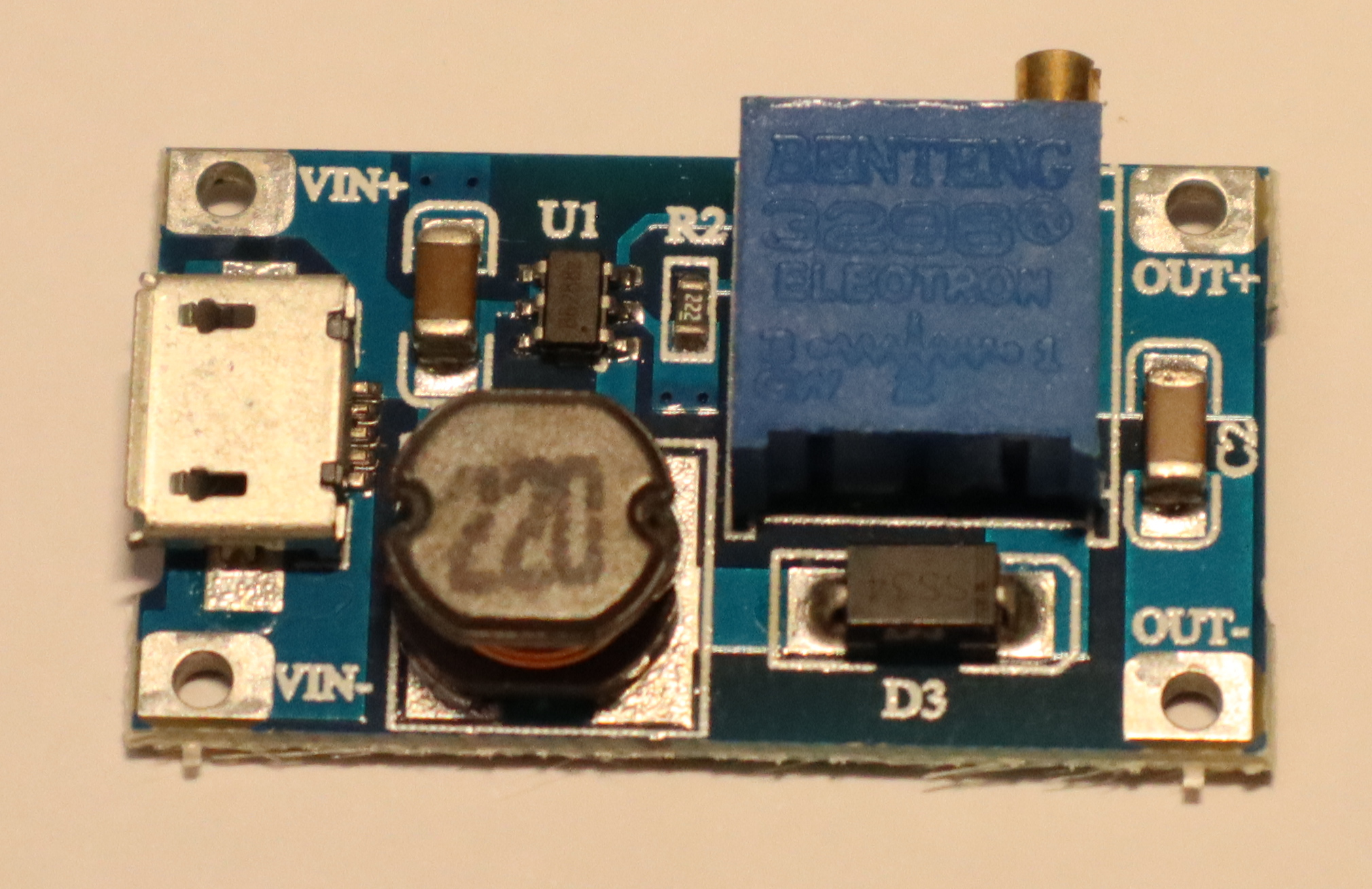
Today's specimen is an MT3608-based step up / boost converter from AliExpress. It's sold with a microUSB input, so boosting 5V from USB to 9V or 12V is a likely application. However, given its low quiescent current, it also seems like a good candidate for boosting ~3.7V from a LiIon battery to 5V for USB.
Specs
Advertised ratings vary. The following conservative estimates might be close to reality.
- Input range: 3V .. 24 V
- Output range: 5V .. 28V
- Maximum input current: 0.8 A (1 A?) continuous, 2 A burst.
- Quiescent current: ~100µA
- Maybe: thermal overload protection
- Maybe: internal 4 A over-current limit
The boost modules I have use a multi-turn potentiometer to configure output voltage.
Application
In this setup, I focused on boosting LiIon voltage to 5V for USB output. LiIon voltage typically ranges from 3.0 to 4.2 V -- I went up to 4.5 V just to gather some more data.
Caution
I took reasonable care to calibrate my readings, but will not give any guarantees. The following results might not be close to reality, and might be affected by knock-off chips and sub-par circuit design.
Output Voltage Stability
Both input voltage and output power of a boost converter can vary over time, especially when powered via a LiIon battery. Its output voltage should remain constant in all cases, or only sag a little under load. Most importantly, it should never exceed its idle output voltage – otherwise, connected devices may break.

Up to about 400 mA output current, the converter is well-behaved. Beyond that (i.e., once its input current exceeds 800mA), its output voltage is all over the place – both below and above the set point. With an observed range of 4.5 to 5.7 V, it is also way outside the USB specification, which states that devices must accept 4.5 to 5.2 V.
So, I'd strongly advise against using this chip to power USB devices that may draw more than a few hundred mA.
At 9V and 12V output, I did not notice issues at up to 400 mA, but did not measure anything beyond that. Also, the measurement setup for these two benchmarks was a bit less accurate.


Efficiency
In low-power operation (no more than a few hundred mA), the converter is quite efficient. Beyond that (i.e., in the unstable output voltage area) its efficiency varies as well.

Further Observations
Once input current exceeds 800mA, the devices I have here emit a relatively loud, high-frequency noise.
TL;DR
Exercise caution to avoid frying USB devices.
All Posts
- A few notes on shell variables
- Software-Defined FM Audio Transmission with ADI / PlutoSDR
- An own package system
- Attaching custom hardware to the parallel port
- Automatically connecting external monitors (udev+xrandr)
- Automatischer Jabberstatus mit zsh und screen
- Avoiding accidental bricks of MSP430FR launchpads
- Backups and Monitoring
- Benchmarking an AliExpress MT3608 Boost Converter
- Bootzeit verkürzen
- Building a test setup for benchmarking buck/boost converters
- Building Python3 Bindings for libsigrok
- Koffeinhaltige Schokolade
- Caffeinated Chocolate
- Check if a filesystem is mounted readonly
- Automatic Screen Rotation on a Chuwi Minibook X
- Code execution hole in feh --wget-timestamp
- Lokalisierung fahrender Züge per GPS
- Debian Lenny
- Installing Debian on a ThinkPad T14s Gen 6 with Intel CPU
- Debian Installer Preseeding for USB sticks (with UEFI)
- Debugging ESP8266 Boot Failures
- Docker Multi-Platform Builds with a Remote Build Host
- Drogen
- EFA-APIs mit JSON nutzen
- Stop IDs in EFA APIs
- Enabling Filesystem Quotas on Debian
- EOS M50 Eyecup / Viewfinder Repair
- Using Deep Sleep on ESP8266 NodeMCU Lua Firmware
- feh v1.13 released
- Checking Maildirs on the Commandline
- Handling USB-serial connection issues on some ESP8266 dev boards
- Fuckup
- Gedanken zur Spackeria
- Gesammelte Logfiles per IRC
- Ghetto Widgets: Putting PNGs onto your wallpaper
- hashl: Hash your files, copy only new stuff
- Hiking the Jizera Mountains (Góry Izerskie / Jizerské hory / Isergebirge)
- Logging HomeAssistant data to InfluxDB
- Wechsel zu ikiwiki
- Introducing check_websites
- Kaputte Symlinks löschen mit zsh
- Krkonoše day 1: Sněžka (snow top) to Soví sedlo (owl pass)
- Krkonoše day 2: Słonecznik: Wetlands, Stones, and Ponds
- Krkonoše day 3: Malá Úpa and Tabule
- Krkonoše day 4: Train trip to Pramen Labe and hike back across the ridge
- LED-Lampen als Ersatz für Halogenbirnen
- Locationfoo
- Using cryptsetup / LUKS2 on SSHFS images
- HTTPS and custom CA certificates with LWP::UserAgent
- Lyrics auf Knopfdruck [aka: Linux ist toll]
- Measurement Automation with Korad Bench Supplies
- Allowing both LDAP login and local account creation on MediaWiki 1.35
- Einstieg in Mikrocontroller-Programmierung
- My coding principle
- Playing Neverball with the Wii Balance Board
- Noch mehr Home-Management-foobar
- Nochmal was zum Paketsystem
- Packaging Perl Modules for Debian in Docker
- Paketsystem #2
- On-demand playback on a remote pulseaudio sink
- PowerCore+ 26800 Teardown
- PowerCore 5000 Teardown and Repair
- Raumtemperaturverlauf ohne Thermometer
- Reading Power Values on a Banana Pi
- Reverse-Tabbing für Nicht-Fische
- Running Linux on a Readonly Root Filesystem
- Running remote nagios checks with an SSH forcecommand
- SanDisk "Sansa Fuze" with Linux
- Semantic Mediawiki Examples
- Logging Steam Deck Hardware Stats to InfluxDB
- Thoughts on embedded environmental sensors
- Monitoring The Things Indoor Gateway (TTIG) via InfluxDB
- Ungelesene Jabber-Nachrichten anzeigen (mcabber + screen/irgendwas)
- Upgrading my Home Assistant / Home Automation Hypervisor to Debian 13 (Trixie)
- USB → DMX with a single UART (e.g. on an Arduino Nano)
- Hiking vacation in the Giant Mountains (Krkonoše / Karkonosze): arrival, Karpacz itself, and departure
- Adding MQTT to Vindriktning particle sensors using an ESP8266 with NodeMCU firmware
- Website stuff
- zsh magic
- "Zwischenrufe" in irssi